• The move to the new server is done. There are some software and database maintenance updates in process. This has us passing the hat around to help out. We appreciate any donations. Seriously, even a dollar helps. The payment page may be found here - https://www.audiokarma.org/support.html

Marantz RS 4000 no sound, need help with voltage amp IC

Hi, I have a little experience with electronics, not so much with receivers from this era...
I already did some research and find this little info:
https://audiokarma.org/forums/index.php?threads/sr4000-in-protect.921629/#post-13954549
https://antiqueradios.com/forums/viewtopic.php?f=13&t=340525

so my parents were watching a movie in netflix, but once the show ends and auto play the next, the sound from netflix autoset to digital, so there’s clipping noise (this time the volume was a little high).... the next time they wanted to turn on the RS 4000 it turned on but with no sound.....

this is so far the tests a have done:

there’s no sound in neither channel A nor channel B (also, no sound from headphones output)

the relay is not "clipping", but I already tested the coil (using 19V from a laptop PSU) and it works fine...

the voltage present in the relay's coil terminals is less than 3V.... (but I don't know why?)

then I did the research and find out that it might be the voltage amp (SKT3062) so I did some tests

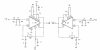
based on a datasheet as well as the schematic diagram from the original service manual I had these results:

the 10,000microF main caps working fine delivering 43V

this 43V successfully energize the voltage amp and I have 43V in the 9th and 7th terminals to ground

then 11th terminal to ground = 3V

and then 5th terminal to ground like 39V the same value for the 6th terminal

so, I think the issue here is that the Voltage Amp blew... but still I’m not sure.

is there any further test I might do before try to find the replace (I think it might be hard to find one of these)?.

some pics
upload_2020-10-12_20-15-12.png
upload_2020-10-12_20-16-47.png
IC34O8WyKEBQEUG6aj7EGHpypVWphi4RouEI2E0dFJ-m2Irlpyo4pDZv705PYgmN-A-1zJDEGvP57fe0lbTLNRDfK4BltsEly1ay2eXgDClOAeXvnEnX8wC8yoHzK7tmNTk10zhkOGFNK9tQWQiMs_PPpwpRu7_H3g6IgoqjZqbQPUUjjQxFWbCVq-JeQ-whw-3UZsiIRvub09P9lXCivLxR3_89A08QkgGmc6ft6HaGUwF7-a81kaU7wDiD9RRXL3HA-NBmO31FUfHI_BymVNrv1oVp1MomVR8hDlbBqqLmvKbjZ37C5m44oIODa3JoZcKS1dQquOdIcPnFVqiOzjY5lCFRllKHDc1t_C6prtmNgLFUQkp1Hf3s4e0TkpgR1WZlh5ZOlFinDg-e-nDof1LBC5xkXUACfPmjsy-L1UzhOAK3ki1iRn8qbXqi1FEKys7Jnrba_ZW3GOcijR8qhtdPs9oDA_-N3XAbUJkSDKv1jqGwBiUPFwK8S0aNWM2V6SJTuHsCEkSCFTeENSuquR4WNsSfxRyomSIxSxjQCcZWf_6bN2j9NAn0l-ecV1UENnFJtd2Y_7Ic2P8nD1BBNaFOEzwpfxCoJzbpsa8NDurgkxyOE6JSiSVblct2VT2mwPd8kKMLbN9BgTYjJUdbPtsik8pbGw29DbkGoSsM1fWEX3fAoAbMVl0EQp4eTW4=w704-h938-no
 
Register to hide this ad
The fact you have only 3 volts on the relay coil is an issue. I would check to see if RN13 (680 ohm 2 watt) is open. look at the voltage on both sides of the resistor. If the 45 volts is present on one side, and there is only 3 volts on the other, the resistor should be getting rather warm. If it is not getting warm / hot, then it is likely open. If it is getting hot, then I would check diode QN07 (across the relay coil) for a short.
 
Last edited:
Hi Bob, thanks for your help and reply
i just do the readings the RN13 resistor is working fine so far... BTW the voltage at that point is 42V
but for the QN07 Zener diode i have a lecture of 0.312 both ways (using diode mode in the multimeter) while the other zener diodes (all being the same model 1S1555) i have .580 in one way as it should be
but how can i know if this probles in not caused by a possible damage in the voltage amp (SKT3062) :S
should i replace the diode and see what happens?

GF1WHXo67aTnaw-gIIh3GNJGYOkiNK_yIy6SkBl3SjT1T3tLOqkyYG2Ey1S_WW9WFnxQVHXO9rX03JUNdAYcFvW9sDJ1-Uqe76gJJ3AUE85E0ghBTExy30dhoxrvfb_OeZUIYRqjxVE0SqcBlNG_H8NnGQ0zcXai7V3cfH3qi1XQQ9nCPVTl6re4_m0dIFZnqfScQ9fY4_gUP-5rVh74_WLXAWSfjziZdqwkS3rQ9Nu3CV_xOMtBWlusbidFgtVP8WmXCeOXCmP7fGW6Rf2k6grTuSwIxfAyXROmgy39StY1rapRCzGoghDldpOlT6a-12AL0ATyyds-9NJ1m-XC4By6xmpoGShVKco71xIQU1y5IRffsGYwdlI5PCWnw5WVScpm5408ns1oXUg7eq3GYk3vJ0xzwuLAEETT-H6dUZI_4bsB82amoA9HZmSNfoSvhaqYxbYgXoC-NsSUTNlRaPTDMuuxD0xWvWxTaoG2GhjiwqfCJtwL6wIwIYOAia8c7untqtZyoHoI4n75xbQn7XJ3sYEiZa0CtOLGigZHpxrwblWhoP4x1oC5Sqol2g87Bc_9TF8nQxJldGUHS7SdSwntAGxBLN0wvjRldSfooCSqA8USOG9dXWFUAv1VqaW-PEYdKrMj9AToxO9XvbHUsc8cP1m-1fweQcbuLW4MNf7BS7WoIPLuSdBDEQv81Tk=w1251-h938-no
 
You will need to lift one end of diode QN07 to get a correct reading. You would see the coil resistance with the diode in circuit, as the relay coil is in parallel with the diode. (BTW it is not a zener diode, but a normal diode). If I understand your first post, you only have 3 volts at the relay coil (or are you saying across the relay coil?). If there is only 3 volts to ground at the relay coil, it would indicate either diode QN07 is shorted or RN13 is open. It appears that the circuit is attempting to turn the relay on, but with a shorted diode or open resistor the relay coil is not getting enough voltage to close. One side of the relay should have at least 12 volts, and the other (the one connected to the transistor) should be very low (less than a volt or so). If you have 42 volts on one end of RN13 and only 3 on the other, then diode QN07 is shorted or RN13 is open. If you have 42 volts on both ends of RN13, then the circuit is not trying to turn on the relay, and you could have a protect condition.
 
ok ok sorry for the delay...
i made a mess with my measurements this is what i have:
RN13 on both ends to ground 42V... across the resistor 0V
in the coil terminals: when i mesured 3V was because i tooked off the relay and then i did the mesure, so those 3V where across the terminals without the coil
with the relay: both ends to ground 42V... across the coil 0V
so... i'm (well not me, the RS4000 :P) in a protection condition, right? now i have a better understanding, still i don't see clearly how if i have 42V in both ends the coil is not working...

thanks, i really appreciate your help
 
OK, the protect circuit is not activating the relay. To activate the relay, QN05 will turn QN06 on, which will pull one end of the relay coil toward ground through RN10. The place I would start is to look at the junction of Q705 and Q703, and also at the junction of Q704 and Q706. They should be almost 0 volts. If one is not, it is causing the protect condition.
 
First - why are we troubleshooting protect circuit?
Your first post indicated that there were some incorrect voltages. The protect circuit will not turn on the relay until these voltages are correct. That is it's function, and it appears to be doing just that. If you correct the voltage problems with the amplifiers, and the protect circuit still doesn't work, then you troubleshoot the protect circuit.

https://audiokarma.org/forums/index...-stk3062-with-stk3062-ii.564657/#post-7408617
The stk30X2 chips are functionally equivalent, but the higher series require external parts that were internal in the original chip. It looks like you just need to add a 15 pF capacitor between pins 4 and 6, and another 15 pF capacitor between pins 10 and 12, the type III version should work.

If you still have issues and suspect the STK 0050 II module, you can test the circuit with out the module be putting 220 ohm resistors between pins 1 and 3, and between pins 0 and 8 where the output modules was. Voltages should be close - do not connect load or speakers. If all is ok, relay should click in....
Good luck.
 
Last edited:
The only reason I focused on the protect circuit was because of the voltages that were stated around the protect relay (3 volts feeding the relay). I was not aware that the voltage indicated was not referenced to ground, but the voltage across the relay coil. That being so I indicated where I would go next, which is to look at the offset in both channels (before the protect relay). If there is a substantial offset in one channel, I would troubleshoot that channel specifically. If both channels have a substantial offset, I would look at something common to both like the power supply or the voltage amp IC. If neither channel has an offset, then I would go back to troubleshooting the protect circuit.
 
thanks Bob, now i have a better understanding, really
Sregor i think changing the voltage amp is the step forward, if after changing it, the protection condition persists i'll che out the power amps
i hope this is all i need to do...
but... i think i didn't understood how to check the STK 0050... i need to disattach the STK 3062 and suply the STK 0050 directly with 42V?

thanks a lot guys
 
well, i'm not busy right now so i worked changing the V amp. I think i did a good work but.... the value in the 5th terminal remains the same (like 39V)
oh man, what a bad luck...
As expected Bob, this values have effect on the Q701 power amd transistors (Q703 and Q705) the values at base to ground are 41V, the values emisor to emisor are 0V, and the values ermisor to groud are 41V. On the Q702 power amp by the other hand, the transistors Q704 and Q706 have these values: base to ground 3.4V, emisor to emisor some milivolts, and emisor to ground some milivolts.

what should i do now.... a new Vamp can`t have the exact same failure as the previous one (maybe i shoud go back the original one later...) should i change the STK0050II?
i didin't understand the way i could test the power amps, should i remove the STK3082 and use resistors????

thanks a lot guys

hdSmJWz49hH-HVNVPTNnhWU4sst5_AT8EWYPKNpwVlDfKZ41wSFtTuiYxnhCuh0wm7Y5zvyPkl3iu-ZBEt7U9QAPvs6xnEZTpPvbMvsLTLzFkBRiN1ngtQ7pFqcvu_pr2bhT643qWJsldpsczrFxI-13uGDd0b5ZPibKrNJAQRp2xclEosBfOUIj9-Tj1yhMWHUa_BG5U9Hz9h17sOuf4jSWeDd81eB2sOC02F6rP4H5ESrWcWfonlNRaXfyA2hY4UxAOlsF_hvwyLF6iWvU5v01OSb7vOpHULc0MBb6ZGMVTHTJ0OOTLwvpnxMKGvgXDqLhV1VYXAfu3Wb1y59r10urtoTw1FL-w9MM0kotntfAhZbhAiDdj3qunz2abJch6lkv4ZwyfQEu0DJlwrJLGCoNSsi0Uyf0N0XmE33W4USI8bPghNWiKxN4iUO7UyUfHQxv45v4nab2byKjvt3OKXB7sqmdAy-FiG5rgf_7miDz6s5Ftpg3lXq5zzKbdkWMsQV9HGKprYWUpGE6U1-mRVZoporyqEYlyrI6zSyZj-bIQkdHsN4RXbD38EOY5lP9mxOPu9Z1jqtwlJAnw55x6sTSvlPxByo-aQrGtDnJzpe_SJB3xKFUd5kGxCWi9jNs4qdm3dHCiL20MvsmKzPiZo_zo9jgcTzwM9EqOaY2pH0kxsuOQlCUQ03HIqSfskg=w1251-h938-no
 
OK guys... so this is it...
i pretend to do this specific post as a little guide of what to do with this kind of recievers... yes, i did it!!!

1.- i think the first step is to test every pin within each power amp and within the voltage amp, THERE SHOULD BE ANY SHORTS (except maybe between pins 8 and 9 or 8 and 7 from the voltage amp)
for example one of the power amps had 2 and 3 pins shorted and this short circuit was damaging the voltage amp.... of course if a short exist you should change that IC... you can change all 3 circuits just take in mind that one of these could be defetive so you should check them before instal them

2.- you should check every diode within the Q701 and Q702 circuits (power amps) if a diod is shorted in these sections, damage may occur to the voltage amp

at this point you should understand that the rele protects the speaker's output as well as the power amps (i think) but if there is something wrong within the power amps or their circuits, there is no protection for the voltage amp
So, if there is a faulty power amp and it's killing a channel in your volatage amp, changing the voltage amp alone will end in the same flaw and you just wasted your money.... and that's what happened to me, that's why there was 42V in the 5th pin from the voltage amp in the first place

then, what did i do? realizing that there was a short in a power amp, i changed it, and since i already changed the voltage amp, i experienced the same issue since that channel was already death, so i changed the voltage amp one more time... at last, the rele activates and i did get sound....

3.- testing the the rele alone may require special tools so, is not as easy but if everithing is fine at this poit you should test the rele

since everithing was ok, i desided to change the caps in the -i asume- the bias and i also changed the other power amp.... so far, the reciever is working fine, but it has a lot of noise (those levels of noise improves within 5 minutes or so...) i don't know if it sounded like that before since this recierver is not mine.... changing the caps definitely improved in some way but it still sounds noisy for me (my parents says that it soubnded like that already, but who knows)..... but testing the volume knob with no sound resulted in extremely low noise, so i asume that the issue here should be other amp stage.

this was a nice experience, really really frustrating but i did it, i couldn't do it without your help, thanks a lot guys

some photos.... those voltage amp's terminals were so damaged that i needed to use cable....

6umLVjfKRvyalpNK9ZQ-QEuxpzv4lYz4ci5kjMBWvKS5Z9_eAwJwZoF0cgStDoThIrZlIMfcCiIrEDGwOYO6nAYYFgi48LqUIojcjd7mCh1FEseN2i-_WTLFPdFpPuQ0fcEt6-hk5BygfopE2jnUB_ijepa6lNldW247NkMDB6HUBsbvfZ7bv3LGRlSbIDd95g89Im_fBFUAZpMC4KfPPcborzrziWYBEIpRSfPObtGPvbYS1KB1Cv5b5wbG0gJxX3YzKLlKPTXl-9yrgQAF8VhHwdRcH-JQvZZs4OywRnJiBy4OezvQoVCq8qhTISnVVLj81J9oNZh60t7idC1IMzDV2i0jXQmmchxZ_OBAzrUoBK125L9aMSjJ92-ATPVeBY7wHN6eOGE3-hJdsbrosKzRCEjuNpnNsf5i_i9GmRG8DgAdnduPuw3ifnGn71uqFXj2Kwv3bs7teq4R0XDufioYAdsRi5gfi0vDa-PYNmzbdEDsYYxtq3aU-6dZeVqa2A_tjva6mpOCm1JguElzTlJyl36GDD4X883_g3npqIWXwjxBHTr2_OzVblFAd5syiHCQVZiSdTZQihPeyCFDKIAC9gE_jIP0PTVe8RtpCl8jLf1g4cdG8KTn4a__EOOMsEPklh41rYufRLi2pOWI2FjD_zoZf4ROcZWdOmquRtV2dtqllIBr5BINHn2hjPU=w1251-h938-no


OrYhQYrYehw3d3Ro-Tuf6Mt4-T17wkCsplLM0MK6K25mRZfIN96UGu9Px0Lt-QxVT4AMVGjp55Zr01W69r9m6_wXGPCcdy250rqc7GVhjHtyvQZFpWrhqfwTd5rSN_mQO4KdInbimsjrsRRjiYYzcLAYjLrrsccK2t-bnCdLwTjzIOv2jmUGT3TPm-x68jPP2oKqNoWe-ct6ihNv7iBLLqkEHeH-T4LAKFkcalEKwiZldGOo5zTtt3sClz91FLvsGNog1qNPdeio6IzygPAFQdRZZEl6roLzJIiK3KUwr-jgUiew9Bv7T7qQTLSxedqh3nPQ8NZ8rTsW_UG029i6pXFXWW8dDRl5H6h4HJeEfxL8Rl7uDSys0pGfx-XV1iz0CgWF-mo6WTnF-W1XiiqxoFoLwcr7djErtiSMNTb3exi9maLMrim_3LdrI4HYAlV_QW594Th6IKabtVuOGEwoo_MZdYZf1IDyvLE07buGLy8PHrHdzKuxL_q5Jf9JHvtPtDOz-sGIOTBZm4fksisY2bzhUE9yM8xZo1h3yalgIxleDfDJ2g47dJW5eOITKgApQMn52XlHGq_C88zYxoO5NDdSvaTmvLRfTJHN4FxDctPL5RSbHxQ_v9ADk8NeDJY2rrkxNC_HCkslGg5UQ7l3bHp1-6-eUtWDaMgNEm-Rfh6K4O8mXIeI5JAH8i7z3cI=w1251-h938-no

vw_MpUkqyQtQ265WRtKwZ-pTxPiom4RNVKazd0yH6DFM0YPk_ys98a9WE0YWKEm-or2bpkx_DEtGXa1F7ZWs7xfkiUCjW_dMDnndDs4EDOtASeRNinrj8SUxzH4Q3PcMqfmtAUWZArPqtCWD_NJQD1ghZELmvwZqBD54mIzaPlOzs21Ti0gwjR3SiZ2hPIYTNaUhBaOL13t0yVsYoCtvKQ9XwjsASXOIJ2DwHGAeJExfLWvhfW32-g84HciySDDVf9kQ0OAmmQsytPVblsyRL5WMAv6H8k2R_-GuQ1QCSLL_FkWTRowIQvDLsPdBYgFSpnOFdSROBPrieFHs57YoMPnN73O7-JfcqWnBO_YY4--j7WbdKXalLPLt0OcjR8r9m5gwOIAznoX0eV0lPFrDrD0cecRWlgvPzhoH4GTsO5N6GwIlX3lTUpWe7Ofr33DStEQH0InXHZKsJCnkHjcSdFE4x-mBsXbqSxZvDDaYw4VZi8KnPfXh53gpZHcCcNbKoViAy8B0qFoAik-iym4M-GCt9J_8TdAUMTLRYn1fFSaKoQI5l18mrc7YWnaktF5A-a_E3XfxOYRH_9xD1fPasQahD_puKhl_N9SDHaWPo9yYSfd9sf5Kd2p3lxST0tT0FrT8hul3XFyLjiKM8H1iCy9chDHk1U2f363N5Gc1-qAC8FTxyietQ5q1yw4yWlE=w1251-h938-no

iDIhn0O-1GD1kLz5y9sDXvzTgle3SsktQ9J8mtz0z-xKMEEXl4CFetOUt0x60Zam4R8L-mftobNanxdA3KpfFuuGy_6lo527MDVjP55ps4bIRYozCgLsQZWnSjmGnG2QGUU5rg9PQw2XQbyecnOAz4g8yzACos9q17xQSo8V9K0O5_F6StCifEbNimq7vEJO1S83T0_XtdhZ4Z27hBj1yUcd9MhzOXwguuOMwXg0AHdwN0rTTUoZq2leAgV0pBKds6iYVWdQVDR5ujtuqqKvmupn9l75m8C08ghZexAWnjY8ezcDvKLLwGJtaCnObmT0dzHJbZo3o3sqxt5FAT1nUuEQXxdSdBI0SvQJ6K8PbGuagC0vY1Ek8OYLM4pWbVBPd8EJsNi1y1iY-FFT04a0JztGMMexww-7qc6O-iH0oFqCOZgbKNYQRiYQ9GsoG13VT9chHhum8UwfyQ9OTkch_sWYmLfRw6LWpHGlmX8pWfxfrQnflVtKRw148GaqF9qcHCYnLBq_vz7M_pCLaGHKgAXP60_rrcXDhnT_UHtdAKX_etgUEgo8mkMavyADBsZXDoBYRdCl3sVsNac_CvYPPBf_amZj7beWmbw55heLmuflgxO9PkzjIXV3krcqwm5dlDX1kRz4kkeJO4ITG63qVFurndkAEt3CX8iavm7Ou97o2ilAkKUDloMHU-WdErs=w1251-h938-no
 
Back
Top Bottom