• The move to the new server is done. There are some software and database maintenance updates in process. This has us passing the hat around to help out. We appreciate any donations. Seriously, even a dollar helps. The payment page may be found here - https://www.audiokarma.org/support.html

Marantz Service Manual error thread

1515

P800
C806 manual says 470uf 35V board has 220uf 35V
C810 manual says 10uf 35V board has 100uf 35V
C818 manual has correct value but doesn't mention that it's bipolar

P400
C414 manual says 100uf 50V board has 100uf 35V
CM01 was installed reverse of board markings and SM
 
Last edited:
1060 Phono Board Version

While this is not an error, it may be an interesting variation.

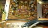
I was working on a Model 1060, serial #33986 this weekend and C901 and C902 on the phono board were Tantalum capacitors.

The copy of the service manual I have shows them as 1uf 25 volt electrolytic's but this may be meaningless due to all of the different production variations of the 1060.

The original Tantalum's measured 2.142uf on my LCR meter and I replaced them with 2.2uf 25 volt electrolytic caps.
 

Attachments

  • Marantz 1060 phono tantalums.jpg
    Marantz 1060 phono tantalums.jpg
    89 KB · Views: 111
  • Marantz 1060 phono tantalums measuring with LCR meter.jpg
    Marantz 1060 phono tantalums measuring with LCR meter.jpg
    75.2 KB · Views: 90
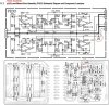
A serious error in PM-350 schematics diagram. +37 and -37V lines are shorted together as shown in the picture.
 

Attachments

  • PM350.jpg
    PM350.jpg
    74 KB · Views: 94
Last edited:
Another funny things with PM-350 schematics.
1. Wrong title
2. CQ22 is shown in a schematic diagram but it can't be found on component board
3. CE23 is on component board but it can't be found in a schematic diagram

Also thanks to nironiro on his suggestions.
 

Attachments

  • PM305-2.jpg
    PM305-2.jpg
    136.8 KB · Views: 47
Last edited:
Marantz 2225 Service Manual Errors


1)

Marantz 2225 Service Manual is incorrect for two capacitors on the "PE01 PRE TONE AMP. BOARD"

The Service Manual lists CE21 and CE22 as both 33uf electrolytic capacitors.

The capacitors as installed from the factory in these locations are 3.3uf electrolytic capacitors.


2)

Also, although not incorrect in value, the Service Manual fails to mention that CE23 and CE24 are actually bi-polar/non-polar electrolytics. The value of 1uf is correct.


3)

In addition, the following test points on the "P800 Power Supply Board" are spec'd incorrectly in the Service Manual:

J805, specified in the Service Manual as 18.5V AC
J806, specified in the Service Manual as 18.5V AC

Both should be around 39V AC


4)

There is an unrecorded electrolytic capacitor on the "P200 FM IF Board". This capacitor has a value of 47uf 10V.

It is located between R251 and R252, near the J211 and J213 test points.

The capacitor symbol is printed on the circuit board and shown in the Service Manual illustration, but it isn't labelled nor shown in the parts list as far as I can tell.


5)

Also, another set of non-polar/bipolar electrolytics not called out in the Service Manual, although are on the schematic and circuit board correctly indicated with no polarity are C305, C306 and C307 on the "P300 MPX Board".


Al
 
Last edited:
2245

MPX P300 board.

C333 and C334, Schematic shows 10uf 16V, Parts list shows 1uf 25V.
Actual parts found on board are 1uf 25V.

C301 missing on parts list. Schematic shows 10uf 10V.
Actual parts on board is 10uf 16V.

C312 parts list shows 22uf 16V, Schematic shows 220f 16V.
Actual part found on board is 220uf 16v
 
Greetings! Thank you for the Marantz service manual errors, very useful. Question: for the idle current adjustment on a Marantz 2275 the text shows to measure J701-702, I don't see those pins, where are they? Thanks!
 
2252

A few discrepancies that I found:
C803 SM says 470uf 50V on the board is 470uf 63V
C809 SM says 1000uf 10V on the board is 1000uf 16V
CE21 SM says 33uf 50V on the board is 3.3uf 50V
CE22 SM says 33uf 50V on the board is 3.3uf 50V
C164 SM says 4.7uf 35v on the board is 22uf 10V
Relay SM says LY2 on the board is an MY2
 
Last edited:
Model 1200 Balance Tests

Page 14, D. Balance Tests

2. Turn the amplifier on and set the SPEAKER switch to SYSTEM 1. Adjust channel A amplifier board potentiometer R504 for an indication of 0V +/- 50mV as indicated on the VTVM.

R504 should be R502.
 
My newly acquired 1060 with WC and 150.

photo9kc.jpg
 
2238b

On the amplifier/relay/PS board (P700), there is an incorrect marking on the board.

Next to post J705, the device marked "R776" is actually a diode and SHOULD be marked "Q754", which is what's actually there.

The schematic is correct, but the component location diagram for P700 in the service manual also shows "R776" instead of "Q754" same as the circuit board, which is wrong.
 
2275

On the parts list for the P700 amp board:

R742 is listed as a 1kOhm trimmer. It should be a 2kOhm trimmer just like R741.
 
2238B schematic errors on P400 - selector board

I found A FEW errors in the 2238B schematic concerning the input selector board P400.

Correction 1:

J210 (AM output) should be connected to J404 (AM input for the selector switch S401), instead of J409 that the schematic shows (which is actually left channel AUX IN). Schematic also erroneously shows J404 not wired to anything.

Correction 2:

J433 should be connected to chassis ground. Schematic erroneously shows J433 left unconnected.

In actuality, J433 is wired to the ground strip across the two large power supply caps (10,000 uF / 50V), which is same as saying it's connected to J706 (ground for the speaker terminals and amp board).

Correction 3:

The schematic for the switch S401-1R (1R = rear-facing side of the first bank) has an incorrect pictorial of the wiper/tabs on the switch.

Tab 9 should have a short leaf on it, so that it can engage the wiper that's shown on the lower half when the selector switch is rotated one notch clockwise into the FM position, shorting Tab 9 and Tab 1. This completes the STEREO lamp circuit, connecting the STEREO lamp to its regulator IC on the FM board. Tab 9 gets connected only in FM mode.

End of Schematic Corrections

I confirmed the pictorial for S401-1F in the schematic to be correct. I also confirmed there are no other errors in S401-1R than what I indicated above. I believe there are no errors in the pictorials for S401-2F, S401-2R, S401-3F, and S401-3R.

Board marking error on Board P400:

The marking on the P400 board of Marantz 2238B indicates a resistor "R432" connected to J439. That is an error, which propagated into the component location diagram for P400 in the SM as well. Instead of "R432", there is actually a diode "Q402". Schematic is correct here.

Component location diagram error on Board P400:

Component location diagram shows resistor R432 connected to post marked "R439". Correction: replace "resistor R432" with "diode Q402" and post "R439" with post "J439".

 
Last edited:
2270 - p550

I haven't seen a note on this but, the polarity of C559 is not marked on the board P550. (The correct polarity is positive faces towards the outside of the board)
 
1090

C805 -- silkscreen shows + in the wrong place (would appreciate it if someone could confirm this). Original cap was wired in with the negative leg in the positive hole.

C806 -- service manual shows 50v, 470 uf capacitor. Actually 50v, 47uf

C421, C422 -- service manual shows 25v, 2.2uf. Actually 50v, 2.2uf

Jack
 
Okay crisis over. I must have had my meter on the wrong setting. Everythings good now.

2220B method is correct for the 2230B.

Maybe there are two types of 2230B. The service manual for both the 2220B and 2230B are wrong for the 2230B I'm looking at.

It looks like they want to measure across the emitter resistors to do the bias setting. The schematic shows J712 and J718 connecting across one side and J713 and J719 connecting across the other side. The board isn't set up that way.

J714 and J716 connect across one set of emitters and J715 and J717 across the other set.

SO.

Connect J714(+) and J716(-) and adjust R733 for 20mV.
Connect J723(+) and J722(-) and adjust R711 for 0mV.
Repeat.
Connect J715(+) and J717(-) and adjust R734 for 20mV.
Connect J724(+) and J722(-) and adjust R712 for 0mV.
Repeat.
 
2238B - Rail Voltage adjustment:
SM says to use pins J722 and J724, should be J722/J728 (ground).
2238B - In place of R-776 there is a diode: Schematic shows Q754 connected to J705 but the board layout shows R776 and so does silk screen.
 
2440 Audio Connects to Power Switch

2440:

The schematic shows the audio signals for all 4 channels (just prior to the Remote/Local selector switch) connecting to the power switch. The power switch is shown to disconnect the audio signals (open circuit) in the OFF position.

What I have seen in three actual 2440 units is that the audio signal at that same point is grounded to the chassis by the power switch in the OFF position and never left as an open circuit.

Edit: Added attached illustration.
 

Attachments

  • 2440 Schematic of Audio at Power Switch.jpg
    2440 Schematic of Audio at Power Switch.jpg
    73.7 KB · Views: 43
Last edited:
marantz 2130

Punker X and Pacific Stereo have mentioned that there are a few FM Alignment errors in the 2130 Service Manual. Can anyone point them out and what the correction should be?
 
Back
Top Bottom