• The move to the new server is done. There are some software and database maintenance updates in process. This has us passing the hat around to help out. We appreciate any donations. Seriously, even a dollar helps. The payment page may be found here - https://www.audiokarma.org/support.html

Marantz SM-7 Problem

dswann01

AK Subscriber
Subscriber
Hoping that some of you guys may be able to help with a recent problem.

I have a Marantz SM-7 amp that I use with a Yamaha CA-810 integrated amp as preamp. While listening at very moderate volume this weekend there was a pop thru the speakers and an immediate drop in volume in both channels to about half the previous output. The VU meters continued to work also, but showed the same output decrease. Increasing the volume level on the Yamaha gave louder output from the amp, but not at normal levels or sound quality. I got the same results with various input sources (CD, streaming, phono). And no obvious smoke or odd smells from the amp either - I had it powered up for 3 or 3 minutes while checking the alternate sources.

To check the Yamaha CA-810 preamp section I put the jumpers back in for it's internal amp and connected speakers directly to it, and all sounds fine with normal volume output - so I don't think my problem is with the preamp or it's output.

So I'm pretty sure the issue is with the Marantz amp. About a year ago the input gain pots were replaced (which adjust the preamp input individually to each amplifier channel), but otherwise the amp is all original as far as I know - and was mfg in 1983. I looked all over the circuitry and did not see any obvious evidence of failure such as burns, capacitor leakage, etc. Also, I bought this amp about 2 months ago and DC offset was less than 20mV for both channels (I don't remember the exact values).

Hoping that some of our Marantz aficionados here can offer some insight into this type of failure or suggestions for investigation. My troubleshooting capability is limited to basic checks with a DMM. Thanks in advance for any and all input!
 
Last edited:
Register to hide this ad
Respectfully asking, anyone have any insights into the issue with my SM-7?

Thanks in advance!
 
I'll offer-up a couple of suggestions for troubleshooting the problem.
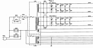
  • Since the problem affects both channels, I would suspect a common circuit such as the power supply.
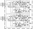
  • The power supply is basically two separate AC to DC converters so it's probably not the issue but check the supply voltages on both sets of +/-65.6V.
  • 1692464710482.png
  • The next thing in common to both is the protection relay contacts. You can measure the AC voltage before and after the relay contacts (with an input signal) to see if there is a reduction in voltage.
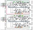
  • Also, check connector JN01 pins for +/- 65V. This circuit is only driven by one of the transformer taps, but it feed both L&R channels so a failure here would be common to both.
  • 1692465214110.png
  • Clean board connector pins with contact cleaner or isopropyl alcohol.
Let us know what you find.
 
I'll offer-up a couple of suggestions for troubleshooting the problem.
  • Since the problem affects both channels, I would suspect a common circuit such as the power supply.
  • The power supply is basically two separate AC to DC converters so it's probably not the issue but check the supply voltages on both sets of +/-65.6V.
  • View attachment 2962850
  • The next thing in common to both is the protection relay contacts. You can measure the AC voltage before and after the relay contacts (with an input signal) to see if there is a reduction in voltage.
  • Also, check connector JN01 pins for +/- 65V. This circuit is only driven by one of the transformer taps, but it feed both L&R channels so a failure here would be common to both.
  • View attachment 2962859
  • Clean board connector pins with contact cleaner or isopropyl alcohol.
Let us know what you find.
Many thanks for the suggestions and insight! And for taking time to provide the circuit diagram snippet.

Dumb question, but what is recommended method to apply an input signal for the protection relay check?
 
If you have an audio signal generator, you can use that, or I think there is a phone app that will generate sine waves. But if you are just looking for passing any type of signal, just hook up your preamp and tuner or whatever input you have and look at the input to the relay. Check the AC voltage at the input to the relay then the output from the relay. If the relay has good contacts, they should be the same.

Is the relay tripping. Do you have an oscilloscope?
 
Last edited:
If you have an audio signal generator, you can use that, or I think there is a phone app that will generate sine waves. But if you are just looking for passing any type of signal, just hook up your preamp and tuner or whatever input you have and look at the input to the relay. Check the AC voltage at the input to the relay then the output from the relay. If the relay has good contacts, they should be the same.

Is the relay tripping. Do you have an oscilloscope?
No oscilloscope. I am an electronics newbie with only a DMM.

I have a couple of tone generator apps on iPad that I can feed into preamp for signal input.
 
I think this may require someone who is more familiar with the SM-7 amp. All I can do is to look at the schematic and guide your troubleshooting, but if you only have a DMM it's a little difficult to find the problem. You can start with basics and measure the outputs of the power supply.

EDIT:
Can you read a schematic and be able to find various connectors and transistor leads to take voltage measurements?

I took another look at the schematic and have these observations:
  1. Independent power supply circuits for L & R channels (with the exception of the transformer) so most likely not the problem since both channels are affected.
  2. L & R amplifier boards are independent for L & R channels, so not the problem.
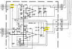
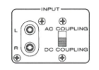
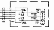
  3. Common Input Board and AC/DC coupling input switch. Could be a source of the problem. For now, put the switch in AC coupling.
  4. 1692545790892.png
  5. 1692544758668.png
  6. Common VU meter driver circuit, but it seems to be indicating what you are hearing, a reduction in the output volume. Most likely not the issue.
  7. Common DC offset detection and relay circuit. Do you hear the relay "click" a few seconds after you turn power on?
  8. +/-73V power supply is separate for L & R channels and feeds DC to the main amps. It is fed from a separate transformer tap, so most likely not the problem. We should be able to measure voltages on the two connectors J801 and J802.
  9. 1692545265323.png
  10. The same amplifier outputs for the L & R "Direct" channels feed both the Sub1 and Sub2 channels. Disconnect any subs that you have connected to these outputs and disengage both sub speaker switches for now to test.
 
Last edited:
I think this may require someone who is more familiar with the SM-7 amp. All I can do is to look at the schematic and guide your troubleshooting, but if you only have a DMM it's a little difficult to find the problem. You can start with basics and measure the outputs of the power supply.
That’s pretty much what I figured would be the case. Lack of knowledge and proper tools is not a good combination for success even with the best guidance. I am going to check the basics if I can.

You know any good techs in the southeast part of the country? I’m in Birmingham, AL.
 
See my edit above.
No, I'm in Southern California. Maybe someone else can suggest someone. I would suggest that you make a new post asking for a Marantz technician in your area and see who responds.
It looks like most (if not all) of the boards are vertically mounted so it might be hard to measure voltages because you can't get onto the board or connectors unless you remove the assembly.
 
Last edited:
See my edit above.
No, I'm in Southern California. Maybe someone else can suggest someone. I would suggest that you make a new post asking for a Marantz technician in your area and see who responds.
It looks like most (if not all) of the boards are vertically mounted so it might be hard to measure voltages because you can't get onto the board or connectors unless you remove the assembly.
Thanks for the additional direction.


OK. Here are the readings I obtained:

This unit does not have the AC/DC coupling switch. So hardwired as AC coupled I believe.

JN01: +62.8V -62.9V

J801: +65.0V +65.1V (not negative on either leg)
J802: +65.6V +64.5V (again no negative)

Measuring directly across the 2 C001 caps was +64.2V -64.2V
Same for C002

Relay clicks normally. Has always been very faint.

Measured DC offset on all 3 speaker outputs. Left and right channels behave the same: right channel 0 to 8 mV left channel 14 to 29 mV
 
Last edited:
J801: +65.0V +65.1V (not negative on either leg)
J802: +65.6V +64.5V (again no negative)
Here are the voltages that I think you should be seeing at J801 & J802. Black lead of DMM to chassis ground, red lead to connector as shown. Can you please double check these.
1692559474255.png
 
Here are the voltages that I think you should be seeing at J801 & J802. Black lead of DMM to chassis ground, red lead to connector as shown. Can you please double check these.
View attachment 2963964
Sorry, my bad at J801 and 802. I gave you the AC in referenced to the blue GND at connector.

New readings:
J801: A +73.2 DC. B -74.2 DC
J802: C +71.8 DC. D -72.1 DC

Danny
 
Hi @dankik

Can I impose on your time and ask a few more questions?

1. After I measured the correct voltages at J801 and J802, those readings were not exactly what you were looking for per schematic, but did they fall into acceptable tolerances (assuming that variation from specified voltages is allowed)?

2. The only check left from your initial recommendations is the speaker protection relay. Looks like I can check the AC voltage before and after the relay contacts using connectors JN04, JN05, and JN06. Another dumb noob question - again would I use chassis ground and use positive lead at each of the 4 points? Assuming using those connections are correct spots - they are at the bottom of the vertically mounted board so the board would have to be pulled up to access the connections. That appears to only require removing 3 screws for mounting bracket - any general advice for this procedure? The mounting bracket appears to protect from shorting any points on back of the board.
IMG_1830 with Protect Board markup.JPG

3. A general question about the input signal from the Yamaha CA-810 integrated amp that I am using for pre-amp. The SM-7 service manual text is Japanese, but it appears that the expected input voltage is 1.5V. The Yamaha pre-out voltage is 3V (I had not checked this before), and I have been running the amp with the input gain pots R001 and R002 at 100% (No trimming of input signal). On the other hand, I listen at moderate volumes with reasonably efficient 8 ohm speakers and judging by the VU meters the amp output is generally 1 to 2 watts at most. Once or twice I may have pushed to 10 watts. Generally at less than 30% volume on the Yamaha, maybe up to 40% volume at times. Always sounded clean.
Do you think I caused any damage by not trimming the input signal to the amp?
 
1. After I measured the correct voltages at J801 and J802, those readings were not exactly what you were looking for per schematic, but did they fall into acceptable tolerances (assuming that variation from specified voltages is allowed)?
These voltages look fine.
J801: A +73.2 DC. B -74.2 DC
J802: C +71.8 DC. D -72.1 DC
2. The only check left from your initial recommendations is the speaker protection relay. Looks like I can check the AC voltage before and after the relay contacts using connectors JN04, JN05, and JN06.
I'm not sure about the board connector access. I would be careful when disassembling and poking around on the boards because you have the 4 large capacitors that might still hold a residual charge that can cause a shock. They should probably be discharged prior to removing boards. Let's see if we there is another way to check voltage elsewhere.
I'll need to study the schematic again to see if the AC is referenced to ground.
3. A general question about the input signal from the Yamaha CA-810 integrated amp that I am using for pre-amp. The SM-7 service manual text is Japanese, but it appears that the expected input voltage is 1.5V.
I think you are correct. 1.5V input is the maximum and the output of your preamp is 3v maximum. If you kept the preamp output at reasonable levels, I don't think that it will be an issue.
 
These voltages look fine.
J801: A +73.2 DC. B -74.2 DC
J802: C +71.8 DC. D -72.1 DC

I'm not sure about the board connector access. I would be careful when disassembling and poking around on the boards because you have the 4 large capacitors that might still hold a residual charge that can cause a shock. They should probably be discharged prior to removing boards. Let's see if we there is another way to check voltage elsewhere.
I'll need to study the schematic again to see if the AC is referenced to ground.

I think you are correct. 1.5V input is the maximum and the output of your preamp is 3v maximum. If you kept the preamp output at reasonable levels, I don't think that it will be an issue.
Thanks dankik. I appreciate any input you feel like you have time for and can safely give.

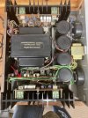
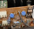
One inconsistency that I found with the schematic for the P-700 power amplifier boards is trimming resistor R720. There are 2 each trimming resistors listed in the parts list, R720 @ 22kohm and R733 @ 1kohm. That is what is installed on the boards (see photos below). However, on the schematic I can only locate R733. The other trimming resistor on the schematic is marked as R726 @ 2.2 kohm. I also found a second R726 @ 2.2kohm on the schematic, and that is the value given for R726 on the parts list.
(Are these the resistors to adjust the bias current and the DC offset?)
IMG_1833.jpg
IMG_1834.jpg
IMG_1835.jpg
 
Hmmm... Marantz SM have been known to contain errors in the schematic. Use whatever is actually on the board. Sometimes the capacitor +/- board markings are wrong also.
 
Last edited:
This is a late follow-up on this thread. Turned out that the problem was actually in my pre-amp, not this Marantz amp.
 
Back
Top Bottom