• The move to the new server is done. There are some software and database maintenance updates in process. This has us passing the hat around to help out. We appreciate any donations. Seriously, even a dollar helps. The payment page may be found here - https://www.audiokarma.org/support.html

May Have Found the Problem - Sanyo P55

KeithTr

AK Subscriber
Subscriber
PXL_20250703_014242117.jpgPXL_20250703_014204502.jpgPXL_20250703_014136203.jpg


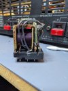
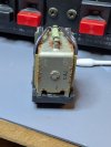
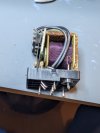
Working on a Sanyo P55 power amplifier that I got quite inexpensively as it was not working properly. It came out of protection but with a bad signal on one channel. It may still not work properly as I found quite a few cold solder joints and a couple of caps way out of spec and it's a real pain to disassemble and it's not reassembled yet. So I replaced all the capacitors trying to be really careful about orientation so I don't have to disassemble again. Plus, the power cord was stiff as a board. But I think these pics may have something to do with the issue on the right channel. Funny thing is there's no rust in the unit and the other relay showed no signs of oxidation.

Separately I do have two question about wiring polarity and testing. I'm installing an IEC inlet and planning on not using the ground. This unit had a non-polarized plug. Can I assume that it doesn't really matter which side of the switch receives the hot side from the wall? Thx in advance.

Secondly, this unit has nearly unobtainable Hitachi MOSFET outputs. All test good. When I hook this back up, can I run a dim bulb test with the output boards not connected and have it be meaningful? Is there anything else I should check before connecting the ouputs?

Thx again for your help...K
 
Register to hide this ad
Power up the relay coil and measure the contact resistance on the two different contacts. That will tell you if it's bad. Resistance should definitely be <50 milliohms. I prefer <20.
 
Power up the relay coil and measure the contact resistance on the two different contacts. That will tell you if it's bad. Resistance should definitely be <50 milliohms. I prefer <20.

Yeah, not going to even try to repair that. Will replace both relays. There's an Omron that apparently drops in when you clip the top row of contacts.
 
Yeah. That relay is junk, throw it in the trash. Since your unit is functioning, you have no need to DBT it.
It would be a very good idea to replace the bias trimmers and pull the outputs, clean them, and reinstall them with new micas and thermal paste as I'm sure the original paste has completely dried out by now.
 
Yeah. That relay is junk, throw it in the trash. Since your unit is functioning, you have no need to DBT it.
It would be a very good idea to replace the bias trimmers and pull the outputs, clean them, and reinstall them with new micas and thermal paste as I'm sure the original paste has completely dried out by now.

This has been a relative pita to disassemble and I'm sure the reverse will be as well. But outputs already out, cleaned, and boards cleaned and touched up plenty of cold/cracked solder joints. Given pain to take apart, I also replaced most capacitors with 105 degrees given it also runs hot (main boards are vertical and get plenty of heat. Planning to replace bias trimmers and remount outputs with silpads (though I could go mica/compound also). I do want to dim bulb it again when back together as I did a lot of touch up soldering and while I was pretty careful and tried to inspect all, I could have introduced a problem.

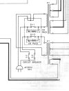
Only remaining plan issue is that old cord (non-polarized) was shot so I am replacing with an IEC inlet and not using the ground. But even though I;ve read some threads here, not quite sure which side of the plug the hot should be wired to - I'm guessing left prong per diagram as that seems to go to switch first. But this unit has circuit breakers, not a fuse, and normally I think you'd wire to go to the fuse first. if you care to comment, I'm attaching that portion of the schematic...

Sanyo P55 power schematic.jpg
 
Hot should go to the power switch. The breakers will function just the same regardless. TBH, I think I'd rather see fuses rather than breakers.
 
I was also going to suggest instead of using an IEC C13/C14, look into IEC C9/C10 for your AC connection.
 
That's a good suggestion for the next one (already mounted the IEC) - but probably harder to find cords at a decent price. But it would preserve (presumably) the original non-polarized wiring scheme.

Seems to me from just mucking around with a multimeter on resistance that it really doesn't matter - both prongs coming in from the outside seem to end at different sides of the switch.
 
Back
Top Bottom