• The move to the new server is done. There are some software and database maintenance updates in process. This has us passing the hat around to help out. We appreciate any donations. Seriously, even a dollar helps. The payment page may be found here - https://www.audiokarma.org/support.html

MC-30 Hum/ hum level pot no effect

AudioWizard

AK Subscriber
Subscriber
I have this MC-30 that has low level hum. Hum control has no effect on the amount of hum, all caps have been replaced, hum pot disconnected and ohmed out ok, output tubes swapped out with other 6l6's, even tried some NOS 1614's no change. Any other ideas?
 
Register to hide this ad
If you have 2 MC30's try switching all the tubes and see if the other one hums. However, I have had my rectifier tube the 5U4GB go bad a couple of times.
 
I believe that the hum balance control is most, if not only effective, when the MC 30`s are connected via the octal socket, and umbilical cable to the period Mac tube preamps, like a C8/C8S providing the high voltage and filament power to the preamp, at least, that was what I remember to be in my case with my 2 MC 30`s and the C8/C8S pair back when I bought them used.

Currently I only own the MC 30`s, and though mine have no hum, what so ever anyway, whether grounded via the 3 prong power cord or not the amps hum balance controls have no effect in any of their position setting.

If you connect your MC 30/s to your speakers with nothing else connected to the amp/s and with the input level control turned all the way off(fully counter clockwise), is there still hum present, ?
If so there is probably some issue with the amp..

You can try flipping the power plug over after you unplug it, and waiting a couple of minutes and re-plugging it back in and waiting until the amp warms back up to see if that had any effect on the hum coming out of your speakers..

Good luck with resolving your MC 30 hum issues, AudioWizard
 
I will the flipping the cord, thanks. The hum is not real bad, but it's there. It's there with the input shorted. I think that I will try to swap in and out some of the early gain stage tubes and see what happens.
 
I will the flipping the cord, thanks. The hum is not real bad, but it's there. It's there with the input shorted. I think that I will try to swap in and out some of the early gain stage tubes and see what happens.

Very good then, Sir.
Keep us informed how it goes.
Good luck tracking it down...
 
Try swapping out the front 12AX7. Uncle Doug's video says it all (don't be fooled by the campy unit). I had a brand new tung sol 12AX7 in my amp and it hummed just like he said. I put in a vintage Telefunken instead and voilà - no hum.
 
Last edited:
I'm probably wrong here, but I was told that the hum adjust was put in for early speakers when permanent magnets weren't strong enough to move speakers easily and speaker manufacturers had coil electromagnets in place of an effective permanent magnet. The hum adjust (IIRC and ANCOB) was put there where the amp could offset hum induced from whatever residual hum the speaker electromagnets made. (BTW; ANCOB= am not completely off base)

I've never verified this, of course. As you're guessing, I'm looking at it now.

OK, it's called a 'field coil loudspeaker.' and I see it on Antique radio sites. I still reserve the right to be wrong.
 
Last edited:
Ok, this is what I done so far;
swapped out the pair of 6L6's for new ones.
tried another NOS 5U4GB, no change.
flipped the power cord , no change.
All of this with the input gain all the way down, hum control no effect. The same hum was there before recap, but with the same tubes.
I will swap out the small tubes and see what happens, maybe Pgena is on to something.
 
Ok back to the little Mac, I swapped out the small signal tubes no change. Looked at the output on the scope, no signal input, the hum is at 120HZ and is approximately 200mv pk-pk. Tried to move some of the point to point wiring around to see if there was any change, sadly no change. Any other ideas?
 
Ok back to the little Mac, I swapped out the small signal tubes no change. Looked at the output on the scope, no signal input, the hum is at 120HZ and is approximately 200mv pk-pk. Tried to move some of the point to point wiring around to see if there was any change, sadly no change. Any other ideas?
I have one here doing the same confounded thing-somebody aIready recapped it, I repIaced a bad hum-adj pot swapped aII tubes- no change

I'm afraid that possibIy the OT isn't canceIIing the hum the way it shouId in a PP (push-puII) amp

I'II be watching cIoseIy
 
Ok back to the little Mac, I swapped out the small signal tubes no change. Looked at the output on the scope, no signal input, the hum is at 120HZ and is approximately 200mv pk-pk. Tried to move some of the point to point wiring around to see if there was any change, sadly no change. Any other ideas?

Can you pop the bottom cover off the MC 30 and take 3 or 4 overlapping close up pictures & post them, AudioWizard ?
 
Can you pop the bottom cover off the MC 30 and take 3 or 4 overlapping close up pictures & post them, AudioWizard ?

Sure, any certain areas you want me to focus on ? I went as far as twisting the filament wires and plate wires from the transformer going to the rectifier and moving the power supply wiring that goes the filter cap away from the rectifier tube wiring to see if there was any change, no. I took the amp from work to my house to see if maybe the commercial building 3 phase wiring might be causing it ( they derive the 120 volts from the 208v), but no change, at least to my ears at home. Tried running a ground from the chassis to the AC outlet ground no change. A question for owners of these amps that have looked at the output on a scope, what are you seeing at idle, no input as far as hum level pk-pk and freq.?
 
Sure, any certain areas you want me to focus on ? I went as far as twisting the filament wires and plate wires from the transformer going to the rectifier and moving the power supply wiring that goes the filter cap away from the rectifier tube wiring to see if there was any change, no. I took the amp from work to my house to see if maybe the commercial building 3 phase wiring might be causing it ( they derive the 120 volts from the 208v), but no change, at least to my ears at home. Tried running a ground from the chassis to the AC outlet ground no change. A question for owners of these amps that have looked at the output on a scope, what are you seeing at idle, no input as far as hum level pk-pk and freq.?

Ok AudioWizard, take a handful of pictures to completely cover the insides.
Also, have you measured with a meter, or scope, set to AC the main filter +, and the tag board bias cap`s - terminals to see what the level of AC ripple is ?
And what does the amplifier draw from the 120 volt source at idle, IIRC it should idle around .8, or less, AC amps.
Also feel the chassis mounted can capacitor, and carefully feel the boards bias cap for unusually elevated temperature.
How well is the replaced chassis mounted cap`s ground tabs are well soldered to the riveted ground plane, and is that ground plane tightly riveted to the chassis ?
Do you know if the amplifier`s power transformer`s primary has been rewired for 120 volts from the original factory wired 115~117 volt tap ?

 
Ok AudioWizard, take a handful of pictures to completely cover the insides.
Also, have you measured with a meter, or scope, set to AC the main filter +, and the tag board bias cap`s - terminals to see what the level of AC ripple is ?
And what does the amplifier draw from the 120 volt source at idle, IIRC it should idle around .8, or less, AC amps.
Also feel the chassis mounted can capacitor, and carefully feel the boards bias cap for unusually elevated temperature.
How well is the replaced chassis mounted cap`s ground tabs are well soldered to the riveted ground plane, and is that ground plane tightly riveted to the chassis ?
Do you know if the amplifier`s power transformer`s primary has been rewired for 120 volts from the original factory wired 115~117 volt tap ?

I will measure the ripple on the on the main filter cap, do you want the ripple at all three points or just the first section of the main cap. I will check the bias cap ripple too.
I will check the draw at 120v at idle. I think a remember about 1 amp, but will recheck.
The main cap is cool. I will check the temp of the bias cap.
The main cap is soldered in three spots to the ground plane. I ran a test jumper lead from the chassis to the cap grounding leads, no change.( i really don't trust those rivets )
It is wired for the 120-125v.

I will measure the items that you requested and report back

All three sections of the main filter, with measured values, if you would.

And if you grasp the filter can does it move much, or at all, if "mildly rocked, or twisted" ??
Close up pictures of the PS area, and the tag board`s bias diode, and cap, when you can, AudioWizard, Sir.
 
Ok, will do. I replaced the filter cap (which was a Spaque twist lock, so probably had replaced before me) with a AuthentiCap which I obtained from a member on here. It is tight to the chassis, soldered to the riveted ground plane in three spots. I will try to get you the info today that you have requested.

Thanks
 
Here is some data;
type A-116B
Current draw at 120v input .875 amps

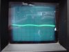
At the first section of the filter coming from the rectifier 429v, 14 v pk-pk ripple, 120 hz,
DSC00670.JPG
After R28, 412v .95v pk-pk ripple,
DSC00671.JPG
After R27, 316v .055v pk-pk ripple
DSC00672.JPG
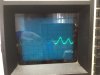
Here is the output, no signal in, gain control turned down, .225v pk-pk 120hz;
DSC00678.JPG
At the bias rectifier, -350v, 1.67V pk-pk ripple, 60hz ( hard to get a good picture)
DSC00675.JPG
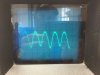
At the grid(s) of the output tubes, bias voltage -42v , what interesting is that the waveform is different between the top and bottom grids. (again hard to get a good picture)
IMG_0944.JPG
IMG_0945.JPG
 
Back
Top Bottom