• The move to the new server is done. There are some software and database maintenance updates in process. This has us passing the hat around to help out. We appreciate any donations. Seriously, even a dollar helps. The payment page may be found here - https://www.audiokarma.org/support.html

MC-30 with variable damping kit

mwa

New Member
I've been plumbing the depths of AK for about a month now, I'm planning on rebuilding my 2 MC-30s. I've had 'em in cold storage for years and now that I'm retired, I have the time.

This will be a first for me. I'm no stranger to vacuum tubes, my experience is with high-powered tubes (e.g. Eimac 4CX15000A).

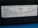
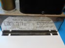
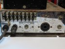
Giving a second look at these MC-30s, I see that both have variable damping. The two are consecutive serial numbers. I'm guessing the DK-30-60 kits must have been used. The output octal socket was replaced with a retrofit plate, riveted in place, such that it looks like the kit could have been applied at the factory.

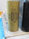
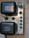
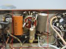
Cosmetically, both units have rusted. It appears that the one pictured below has previously been rebuilt, judging from the 80-40-30-20 can 'lytic.

If anyone has documentation on the DK-30-60, I'd sure appreciate it. Pix below.IMG_0820 (Medium).JPG
 

Attachments

  • IMG_0817 (Medium).JPG
    IMG_0817 (Medium).JPG
    62.3 KB · Views: 27
  • IMG_0818 (Medium).JPG
    IMG_0818 (Medium).JPG
    83.4 KB · Views: 26
  • IMG_0819 (Medium).JPG
    IMG_0819 (Medium).JPG
    75.6 KB · Views: 25
  • IMG_0821 (Medium).JPG
    IMG_0821 (Medium).JPG
    95.8 KB · Views: 28
Register to hide this ad
Try emailing the factory. I think the MC-30's with that option from the factory were designated as MC-30A
 
Maybe a factory special circuit request option for the amps intended use in a industrial application, like say a shaker table, etc. ?
 
Your guess is as good as mine: I have no idea of the history, other than at one time, the amp was used in a PAGING SYSTEM! Huh??
One of the amps has a label on the gain pot "paging". And on the barrier strip in the photo you can see a label "70.7".
I'm baffled why anyone would use these amps in such an application. Go figure.
 
Good luck with your MC30's. Looking forward to updates. They will definitely be worth it when you are done. Music always seems to sound better when you use equipment you worked on. Paul.
 
Your guess is as good as mine: I have no idea of the history, other than at one time, the amp was used in a PAGING SYSTEM! Huh??
One of the amps has a label on the gain pot "paging". And on the barrier strip in the photo you can see a label "70.7".
I'm baffled why anyone would use these amps in such an application. Go figure.
Many types of McIntosh amplifiers were used in industrial and commercial applications. As a result of their potential use in these fields many McIntosh output transformers were wound with output windings for 70.7 volt "constant current" speaker distribution systems. Your A-116b's were no exception.
 
In general, my plan is to first: understand and document these variable damping circuits.

I'm presently going through this unit measuring resistances of the existing circuit, documenting against the publish specs.

Then prior to rebuild, I'll disassemble the components and measure each resistor & cap. Most of the resistors are carbon composition.

I will replace all resistors with metal film 1% where possible. The 12k R19 & R20, I'll order a quantity of 12k 1% and match as close as possible. Coupling caps where possible will be polypropylene.

The idea is to get the amps as close as possible to the original design center, using superior components generally unavailable at the time of design.

The only real mods I anticipate is replacing the selenium diode (already been replaced with silicon), adjusting values of R30 and C13.

The variable damping kit includes a pot with an off switch, and looks like a couple caps and inductors (see photo).

I know this is going to take a long time. I've had these beasts in storage for many years, a few more months won't hurt.
 

Attachments

  • IMG_0827b (Medium).JPG
    IMG_0827b (Medium).JPG
    103.7 KB · Views: 22
They were very expensive, and fair bet the carbon comp were sufficient to get the required specs. You may improve the specs, but its a question of how much cost to get how much benefit

Easier now, CC parts are the more expensive items now.

For the variable damping, I'd expect to see it sitting between the output transformer secondary and the speaker load somewhere so it can develop voltage based on the current flow through the speaker. Its a current based feedback system, where the usual setup is voltage based.
 
There were a lot of film caps in my MC240, I think that there are some in my MC75s also. When I was designing, I used what was necessary and if the circuit didn’t benefit from a higher-precision or more expensive technology, I didn’t use it. In some cases, most really, it just doesn’t make a difference and in some it isn’t as good (there are different characteristics between a foil electrolytic cap and a film cap, so better or just different regarding SQ?). Carbon resistors also have slightly different characteristics, especially related to temperature, so is that intentional, irrelevant, or is there some additional SQ to be had? I’d imagine that the warm-operating values of these components are what’s important to replicate not the datasheet. Most of the people recommending wholesale changes to different technologies are not EEs, most have not designed audio equipment (or similar electronics, especially tube-era) for a living, and none know why McIntosh Engineers made the choices that they did.

It is easy to see what was installed, much more difficult to determine why. Many people are convinced that spending a lot more money on capacitor “upgrades” is money well spent, there is an entire industry around that belief. Whether it is true or good quality original type will yield the same result is something clouded in hype and I can’t claim to know the answer.

For me I like to use good commercial-quality components, sometimes I prefer film in the audio path, sometimes I prefer metal-film, but each component serves a specific purpose and I’m not convinced that changing a voltage-divider’s resistors from one technology to another will do anything to improve the sound (for example), but it might be a better choice for long-term stability.

To each his own, this hobby is as much religion as it is science, and whatever makes you happy is the best choice.

Edit:

One thing that I have found however, is that carbon-comp resistors in some values are getting very hard to find, which makes it much easier to abandon the technology and just replace with metal-film.

Also, I notice that my new McIntosh amplifiers, ... still have a fair number of electrolytic caps in them, which again is a reminder that they are better for some parts of the circuit as McIntosh would just use all film caps if it was a better choice.
 
Last edited:
They were very expensive, and fair bet the carbon comp were sufficient to get the required specs. You may improve the specs, but its a question of how much cost to get how much benefit

Easier now, CC parts are the more expensive items now.

For the variable damping, I'd expect to see it sitting between the output transformer secondary and the speaker load somewhere so it can develop voltage based on the current flow through the speaker. Its a current based feedback system, where the usual setup is voltage based.
I agree. If I can't get actual documentation, I'll trace it out.
[ps] Probably will anyway....
 
Last edited:
There were a lot of film caps in my MC240, I think that there are some in my MC75s also. When I was designing, I used what was necessary and if the circuit didn’t benefit from a higher-precision or more expensive technology, I didn’t use it. In some cases, most really, it just doesn’t make a difference and in some it isn’t as good (there are different characteristics between a foil electrolytic cap and a film cap, so better or just different regarding SQ?). Carbon resistors also have slightly different characteristics, especially related to temperature, so is that intentional, irrelevant, or is there some additional SQ to be had? I’d imagine that the warm-operating values of these components are what’s important to replicate not the datasheet. Most of the people recommending wholesale changes to different technologies are not EEs, most have not designed audio equipment (or similar electronics, especially tube-era) for a living, and none know why McIntosh Engineers made the choices that they did.

It is easy to see what was installed, much more difficult to determine why. Many people are convinced that spending a lot more money on capacitor “upgrades” is money well spent, there is an entire industry around that belief. Whether it is true or good quality original type will yield the same result is something clouded in hype and I can’t claim to know the answer.

For me I like to use good commercial-quality components, sometimes I prefer film in the audio path, sometimes I prefer metal-film, but each component serves a specific purpose and I’m not convinced that changing a voltage-divider’s resistors from one technology to another will do anything to improve the sound (for example), but it might be a better choice for long-term stability.

To each his own, this hobby is as much religion as it is science, and whatever makes you happy is the best choice.

Edit:

One thing that I have found however, is that carbon-comp resistors in some values are getting very hard to find, which makes it much easier to abandon the technology and just replace with metal-film.

Also, I notice that my new McIntosh amplifiers, ... still have a fair number of electrolytic caps in them, which again is a reminder that they are better for some parts of the circuit as McIntosh would just use all film caps if it was a better choice.

Well yes: I'm not an EE and I haven't designed audio gear. I make no such claim. And I believe that the McIntosh designers knew/know what they're doing; I'm not inclined to change the design but rather to bring it back to its original performance (the one exception noted above).

I do have some electronics training and lots of experience so I know a little bit about the subject.

I also understand that there's still a place for 'lytics, and I did not indicate that I'd replace ALL caps with polypropylene. The 'lytics will probably remain, albeit with new ones of the same value.

Before making any changes, I'll be checking each component's value. Given the age, I'm betting that many have changed value, especially the 'lytics.

Agree with you that carbon composition resistors have become expensive and hard to find.

Regards,
-- Marty
 
I have to admit, I’ve changed my vote over the years and just replace replace replace in many cases. Although many EL caps might test okay, be sure that you can test them at their rated voltage. A good cap analyzer that can do that is nice to have, or you can simply replace them and not worry about it. Most consumer-grade (especially battery powered) capacitor testers/analyzers can’t test at tube-audio voltage (600V?).

The original caps in some/many cases are still performing within spec (I’ve found this to be true of many main PS caps in vintage McIntosh equipment) but they also can be near failure, and it isn’t worth tearing into it twice. I love the freedom of walking away with my audio system running, and not worrying about parts I didn’t replace. OTOH, I have read about fairly new CE caps failing, so there is that, ... no perfect solution?
 
When I was designing, I used what was necessary and if the circuit didn’t benefit from a higher-precision or more expensive technology, I didn’t use it.

If you could go back in time to talk with the original engineers, I'd bet you their answer as to why they used specifically what they used will be basically this. I highly doubt it was selected by a mystical set of greybeards sitting around a breadboarded amp and swapping components one by one until it was magically "voiced" to whatever they deemed correct.
 
Yes, I agree entirely. It usually boils down to what the circuit requires, performance and cost.

Certainly the circuit requirements haven't changed. Costs have.

Some small improvement might be possible by using modern components with better performance, while staying true to the design.

While metal film resistors may have been available at the time, maybe they were too expensive?? Idunno.

If I had a beard, it would be grey. Nevertheless I'm sold on the original design concept.
 
Years ago I read about a pair of Mc tube monoblocks (MC30/60?) discovered in the basement of a CBS recording studio that were similarly modified.
 
Variable damping was kind of a design phase amplifier manufacturers went through. The designer of the AR-3 loudspeaker insisted the the best sound from a tube amp for his speakers was with an amp with a damping factor of 1. So Marantz model 8 and 9 and in this case the MC 30 had variable damping.

When the ML series of Mac speakers came out the speakers were said to be critically damped meaning they wouldn't ring or resonate no matter which amp you chose. All you had to do was select the preferred bass curve from your MQ equalizer depending on where you located the speakers in your listening room and your listening location. So it didn't matter if you chose a MC 275 or a MC 2505 because the bass quality was determined by the acoustic suspension enclosure, the placement in the room, the room EQ and not so much by the amp you chose. Where speakers in infinite baffles room positioning and type of amp made a bigger difference. Same goes for ported speakers and their cousins but not to the same noticeable extent was my experience. Of course the famous Corner horn had to go in a corner as did some EV, Altec, JBL. Jensen and Frazier speakers back in the 50's and early 60's.
 
In general, my plan is to first: understand and document these variable damping circuits.

I'm presently going through this unit measuring resistances of the existing circuit, documenting against the publish specs.

Then prior to rebuild, I'll disassemble the components and measure each resistor & cap. Most of the resistors are carbon composition.

I will replace all resistors with metal film 1% where possible. The 12k R19 & R20, I'll order a quantity of 12k 1% and match as close as possible. Coupling caps where possible will be polypropylene.

The idea is to get the amps as close as possible to the original design center, using superior components generally unavailable at the time of design.

The only real mods I anticipate is replacing the selenium diode (already been replaced with silicon), adjusting values of R30 and C13.

The variable damping kit includes a pot with an off switch, and looks like a couple caps and inductors (see photo).

I know this is going to take a long time. I've had these beasts in storage for many years, a few more months won't hurt.

film caps are likely going to be way too large to fit in there. Looks like one cap is a 100uf 3V. You may want to try a nichicon bypolar cap with a .33uf film by pass on it first.
my guess is the pot is in the feedback loop for the first tube. You can calculate the knee in the curve for the various parts changes. Usually above a certain frequency the feedback goes to a very high value to reduce oscillation potential.
 
Back
Top Bottom