Lost Cause
New Member
First time poster, long time lurker. I'm hoping for some gentle guidance on resolving an issue with my MC2015. It has been an eBay/Covid disaster thus far.
With no experience in electronic repairs, and limited tools, just using advice given others on this site I've actually managed to resolve many of the issues. But at least one remains . . .
Remaining Issue:
When gain dial is set above 9 O'Clock, the Right channel puts out distortion though the speaker. The distortion increases as the gain increases, but the sound level stops increasing (both audibly and as displayed on the meter). As if all the increased power is going to increased distortion instead of increased volume.
Running test signals through, the channel seems to be fine at the higher end. I've tested 15khz down to 1khz and I don't seem much issue. However, the lower the sound gets, the worse the distortion (and volume limit) gets.
When I bring the test signal down to 50hz and below, there is clearly some sort of signal issue, as it puts out a thumping sort of sound. At 20hz, the left channel is completely quiet (as its below the speaker's range) but the right channel sounds like a helicopter is hovering outside. Thump, thump, thump, thump . . .
Note that the right channel sounds fine through headphones, whether the speakers are switched on or off.
Left channel sounds fine to my ears, with speakers or headphones.
The Direct/Normal switch doesn't seem to do anything, good or bad. Also, I tried connecting the speakers to the different 4/8/16 ohm hookups, didn't seem to change the issue.
System:
Speakers are Heresy I's. I've also tried small 4ohm speakers to confirm the speakers aren't the issue.
Input sources I've tried (all with the same results) are:
When I first powered up the amp, its sounded fine for a minute and then the fuse below. I went though a few fuses before I realized the issue was not the fuse.
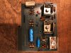
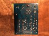
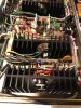
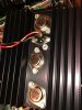
After some testing, I replaced all 3 Motorola transistors on one of the four heatsink output boards. That kept the fuse from blowing.
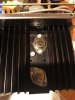
Next was an issue where the right meter would "peg" when I switched off the speakers. Seemed like there was some sort of short. While I don't have the ability to test transistors, I did a continuity test and two of the remaining Motorola transistors tested as having continuity. So, to be safe (and maintain consistency) I just replaced all 12 of the big Motorola transistors with ON MJ15003G from Allied. Meter issue resolved.
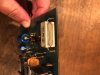
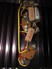
I also switched around the two smaller boards (with smaller transistors) between the heatsinks, to see if that made a difference. Didn't seem to, so I figured those were fine.
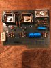
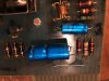
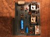
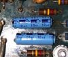
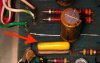
Then I noticed the two original 470uf 25v capacitors had been replaced by two mismatched caps, both of which I removed and measured - they were way out of spec. I was hopeful these caps could be the cause of the issue. I replaced them with 470uf 25v Nichicon caps. Didn't seem to make a difference.
On the aesthetic side:
This is my first McIntosh purchase. I had been looking to match an amp up to my second hand Klipsch Heresy I's. While visiting a restaurant in Nashville, I noticed the background music sounded bright and clear. I checked the walls and saw an old pair of Heresies hanging, hooked up to walnut encased McIntosh amp and preamp. I fell in love with the vintage sound then and there.
Then I made the mistake of buying a well priced MC2105 (in Walnut case) off eBay from a seller/scammer in California.
Amp arrived in a thin, overly-large cardboard box, partly crushed, and unprotected by the minimal (and popped) bubble wrap. Front glass was shattered, all the lights broken, complete mess.
Tried to return through eBay, the seller disputed my claims and eBay demanded I get a third-party damage assessment. But by then, the Covid shutdown was in full force. Due to closures, I was not able to get the assessment.
With a muti-month Covid shutdown looming, I embarked on my first electronic repair project. And here I am, surrounded by screws and plates and random parts, hoping for your help!
With no experience in electronic repairs, and limited tools, just using advice given others on this site I've actually managed to resolve many of the issues. But at least one remains . . .
Remaining Issue:
When gain dial is set above 9 O'Clock, the Right channel puts out distortion though the speaker. The distortion increases as the gain increases, but the sound level stops increasing (both audibly and as displayed on the meter). As if all the increased power is going to increased distortion instead of increased volume.
Running test signals through, the channel seems to be fine at the higher end. I've tested 15khz down to 1khz and I don't seem much issue. However, the lower the sound gets, the worse the distortion (and volume limit) gets.
When I bring the test signal down to 50hz and below, there is clearly some sort of signal issue, as it puts out a thumping sort of sound. At 20hz, the left channel is completely quiet (as its below the speaker's range) but the right channel sounds like a helicopter is hovering outside. Thump, thump, thump, thump . . .
Note that the right channel sounds fine through headphones, whether the speakers are switched on or off.
Left channel sounds fine to my ears, with speakers or headphones.
The Direct/Normal switch doesn't seem to do anything, good or bad. Also, I tried connecting the speakers to the different 4/8/16 ohm hookups, didn't seem to change the issue.
System:
Speakers are Heresy I's. I've also tried small 4ohm speakers to confirm the speakers aren't the issue.
Input sources I've tried (all with the same results) are:
- iPhone and Amazon Alexa direct to the amp.
- iPhone though a cheap tube preamp.
- iPhone though a 1970's Kenwood amp's "main out."
- iPhone though the tube preamp and then though the Kenwood.
- FM Radio from the Kenwood amp's "main out."
When I first powered up the amp, its sounded fine for a minute and then the fuse below. I went though a few fuses before I realized the issue was not the fuse.
After some testing, I replaced all 3 Motorola transistors on one of the four heatsink output boards. That kept the fuse from blowing.
Next was an issue where the right meter would "peg" when I switched off the speakers. Seemed like there was some sort of short. While I don't have the ability to test transistors, I did a continuity test and two of the remaining Motorola transistors tested as having continuity. So, to be safe (and maintain consistency) I just replaced all 12 of the big Motorola transistors with ON MJ15003G from Allied. Meter issue resolved.
I also switched around the two smaller boards (with smaller transistors) between the heatsinks, to see if that made a difference. Didn't seem to, so I figured those were fine.
Then I noticed the two original 470uf 25v capacitors had been replaced by two mismatched caps, both of which I removed and measured - they were way out of spec. I was hopeful these caps could be the cause of the issue. I replaced them with 470uf 25v Nichicon caps. Didn't seem to make a difference.
On the aesthetic side:
- I replaced all the broken lamps with LEDs. They look great and are cool to the touch.
- The blue acrylic covering for the meters had shattered, so I cut my own. They turned out perfect, actually.
- I've held off dropping $250 on new front glass until I get things resolved.
This is my first McIntosh purchase. I had been looking to match an amp up to my second hand Klipsch Heresy I's. While visiting a restaurant in Nashville, I noticed the background music sounded bright and clear. I checked the walls and saw an old pair of Heresies hanging, hooked up to walnut encased McIntosh amp and preamp. I fell in love with the vintage sound then and there.
Then I made the mistake of buying a well priced MC2105 (in Walnut case) off eBay from a seller/scammer in California.
Amp arrived in a thin, overly-large cardboard box, partly crushed, and unprotected by the minimal (and popped) bubble wrap. Front glass was shattered, all the lights broken, complete mess.
Tried to return through eBay, the seller disputed my claims and eBay demanded I get a third-party damage assessment. But by then, the Covid shutdown was in full force. Due to closures, I was not able to get the assessment.
With a muti-month Covid shutdown looming, I embarked on my first electronic repair project. And here I am, surrounded by screws and plates and random parts, hoping for your help!