wizage
New Member
Just starting my journey restoring a MC2105 that was beat to crap on shipping. I ended up getting a refund and get to keep the amp but it needs some love. Starting a thread of the journey and all the issues that I have along the way.
Assess the damage
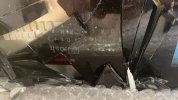
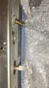
The first step was taking out all the glass and thankfully the plexiglass survived with a few cracks. After I got the plexiglass off the amp I found that the knobs were not where they were supposed to be and the actual metal under the glass was also pretty dinged up. I then took a look at the two pots that taken the most damage (assuming this from the fact that the metal near them were warped. The two effected pots were the speaker switch and the left gain knob. The speaker switch seemed to operate just fine so didn't dive into that one. The left gain knob though was exploded from the back so I decided to take it apart to make sure the wafer survived. While the wafer survived the threading on the knob and the actual plastic piece that holds the rod were cracked making the rod unstable and wobbles a lot allowing you to even "wobble" your way to the other side of the pot bypassing the stop. So the pot will need to be fixed up, that will be later tho. I pulled the rest of the front off to find that I lost a few bulbs also in the bouncy journey to my house. Other then that nothing else seems to be damaged, so time to fix it up to see if the amp will turn on. I do see a bit of corrosion from the big caps but we will get to that later.
Repairing the damage
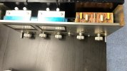
After pulling the entire front metal panel off the amp I was able to see the damage of the metal sheet which was pretty bad. I was able to find some wood in my garage and carefully reshape the metal back as flat as possible. I had to do this otherwise the knobs wouldn't mount properly and fit whenever I replace the glass. After a lot of banging around in the garage the metal sheet seems to be flat as I will get it for now. I then took some Locktite super glue to the cracked pot to stabilize the rod enough to be used (it still wobbles and I will be looking at doing a replacement if everything else in the system works). I had buy a die to re-thread the pot so I could reattach it to the front of the metal front, thankfully this just needed a bit of muscle to it done.
Power on test
After finally mounting everything back to a straight enough metal sheet I finally did a power on test. I did confirm that the knobs/meters seem to be working but the output to the speakers was a bit lacking so def need to spend the time to recap and go through all the components to validate they are working. This is what I am working through now.
Re-cap (just the start)
I have ordered some new high filter caps. Everyone suggested from AudioKarma either the E36D750CPN393QEB7M or 36DY393F075DL2B which sadly both or no longer being sold. So I found a replacement that just seems like the newer version which is a E36D750HPN393TE92U. So I have on order a full recap for the high filter caps, the two output boards, the can caps from Hayseed Hamfest (showing some leaks there), and also looking at doing the thermal upgrade from the service bulletin.
Next steps
In the meantime, if anyone that has replaced the gain pots on a MC2105 (or similar amp) have any recommendations for pots to get that would be great. I have heard I most likely will have to mod my knobs to fit new pots and I can't seem to find in any of the spec sheets what the pots range is.
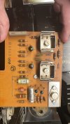
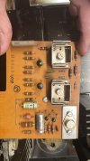
Also I am looking to see if anyone has done the service upgrade where they are missing C117 & C118, I am making sure I don't need to add in the C117/118 or the values need to be different or I need to replace a cap somewhere else in the amp.
Going to be putting a lot of love into this amp, should be a journey. Cheers
Assess the damage
The first step was taking out all the glass and thankfully the plexiglass survived with a few cracks. After I got the plexiglass off the amp I found that the knobs were not where they were supposed to be and the actual metal under the glass was also pretty dinged up. I then took a look at the two pots that taken the most damage (assuming this from the fact that the metal near them were warped. The two effected pots were the speaker switch and the left gain knob. The speaker switch seemed to operate just fine so didn't dive into that one. The left gain knob though was exploded from the back so I decided to take it apart to make sure the wafer survived. While the wafer survived the threading on the knob and the actual plastic piece that holds the rod were cracked making the rod unstable and wobbles a lot allowing you to even "wobble" your way to the other side of the pot bypassing the stop. So the pot will need to be fixed up, that will be later tho. I pulled the rest of the front off to find that I lost a few bulbs also in the bouncy journey to my house. Other then that nothing else seems to be damaged, so time to fix it up to see if the amp will turn on. I do see a bit of corrosion from the big caps but we will get to that later.
Repairing the damage
After pulling the entire front metal panel off the amp I was able to see the damage of the metal sheet which was pretty bad. I was able to find some wood in my garage and carefully reshape the metal back as flat as possible. I had to do this otherwise the knobs wouldn't mount properly and fit whenever I replace the glass. After a lot of banging around in the garage the metal sheet seems to be flat as I will get it for now. I then took some Locktite super glue to the cracked pot to stabilize the rod enough to be used (it still wobbles and I will be looking at doing a replacement if everything else in the system works). I had buy a die to re-thread the pot so I could reattach it to the front of the metal front, thankfully this just needed a bit of muscle to it done.
Power on test
After finally mounting everything back to a straight enough metal sheet I finally did a power on test. I did confirm that the knobs/meters seem to be working but the output to the speakers was a bit lacking so def need to spend the time to recap and go through all the components to validate they are working. This is what I am working through now.
Re-cap (just the start)
I have ordered some new high filter caps. Everyone suggested from AudioKarma either the E36D750CPN393QEB7M or 36DY393F075DL2B which sadly both or no longer being sold. So I found a replacement that just seems like the newer version which is a E36D750HPN393TE92U. So I have on order a full recap for the high filter caps, the two output boards, the can caps from Hayseed Hamfest (showing some leaks there), and also looking at doing the thermal upgrade from the service bulletin.
Next steps
In the meantime, if anyone that has replaced the gain pots on a MC2105 (or similar amp) have any recommendations for pots to get that would be great. I have heard I most likely will have to mod my knobs to fit new pots and I can't seem to find in any of the spec sheets what the pots range is.
Also I am looking to see if anyone has done the service upgrade where they are missing C117 & C118, I am making sure I don't need to add in the C117/118 or the values need to be different or I need to replace a cap somewhere else in the amp.
Going to be putting a lot of love into this amp, should be a journey. Cheers
Attachments
-
 frontpanel2.jpg81.2 KB · Views: 117
 -
 current_outputboard_missing117.jpg91.4 KB · Views: 119
 -
 pretty_straight.jpg97.4 KB · Views: 112
 -
 askew_under.jpg71.3 KB · Views: 113
 -
 crackedpot.jpg51.4 KB · Views: 113
 -
 destroyed-thread.JPG94.4 KB · Views: 113
 -
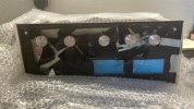 frontplate.jpg109 KB · Views: 113
 -
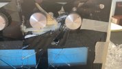 knobs_askew.jpg79.3 KB · Views: 117
Last edited: