
• The move to the new server is done. There are some software and database maintenance updates in process. This has us passing the hat around to help out. We appreciate any donations. Seriously, even a dollar helps. The payment page may be found here - https://www.audiokarma.org/support.html

Mc240 Cathode Follower 12ax7 tube recommendations please

Paul K

Active Member
I am confused about what tubes should go into this position as I understand they get run a bit hard there.
I have new production tubes and am not certain if they are safe there either.
I also would like to know if those tubes should be matched and measure high GM to have maximum effectiveness. Also are the tubes with spiral filaments a no-no?
I've included a voltage chart for purposes of reference.
Thank you all for helping me sort this out!
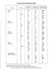


Screenshot_20210702-203942_Drive.jpg
 
Register to hide this ad
If they are the same number, they are safe. Also, I don't think they really get run hard compared to output or power handling tubes but I am not familiar with Mac stuff.

Most cathode follower tubes are known as preamp tubes and supply drive to the output tubes.

Matched tubes USUALLY pertains to the output tubes.
 
Last edited:
Mac gear is a little different than most though. The cathode follower in this actually directly couples to the grids of the output stage, so problems with the 12ax7 mess with how the output stage biases.

Looking at the voltage and current here these really do get worked hard. Notice plate volts are at 430, cathode is at -46 so these see 476 volts DC across a tube rated for 300. Its running about a little under 1ma of current based on some voltages from the Sams and working out the voltage drop across those two 56k resistors, but that ends up being 4+ watts of plate dissipation on a tube rated for 1 watt.

as to what you should put there, frankly I have no idea. Probably a question more fitting for the McIntosh sub-forum. Just based on where it is, I'd think matched sections would be a not awful idea though. Each half of the tube runs one side of the output stage, so if you want equal but opposite output you need a tube that both sides act basically the same. If someone makes an extra-stout 12ax7 that wouldn't be a bad thing to use.
 
er, yeah, decimals. Dave is right, its 0.4 watts, not 4 watts. apparently I need an extra set of toes or something.
 
Do what McIntosh did on the 75-Watt variants; use a 12AT7.

Also, for any ov these amps, keeping the fixed, fixed bias scheme is just nuts. Hide a pair of adjustment pots under there.
cheers,
Douglas
 
Perhaps you should study and actually understand these circuits before offering ridiculous suggestions.....
 
My dearest arts, if you'd be so kind do please expound a wee bit about 'ridiculous suggestions'. Like exactly why they are 'ridiculous'. Be thorough... :D
cheers,
Douglas
 
Do what McIntosh did on the 75-Watt variants; use a 12AT7.

Also, for any ov these amps, keeping the fixed, fixed bias scheme is just nuts. Hide a pair of adjustment pots under there.
cheers,
Douglas

How does one place a pair of adjustment pots in this unit?
 
How does one place a pair of adjustment pots in this unit?
Unless "one" possesses good soldering skills, the proper test equipment to set the bias to and the knowledge of what pots to use plus a desire to venture off the beaten path, "one" does not. However, there are those who enjoy and even seek out the path least taken.
 
How does one place a pair of adjustment pots in this unit?
I don't recall off hand exactly what the value of the cathode follower's grid biasing network is, but one reduces both the neg to ground and the grid to neg, and add a pot of the missing value at the node. The cathode follower grid then goes to the wiper. There is less risk to overbiasing a power tube; you can set idle EXACTLY where you want it. You can also account for small differences in idle current that eat up OPT flux density needlessly, hindering full power low frequency response.

Have to measure DCIR of the OPT's primary( the cathode winding ) so you can get the R for use in Ohm's Law. The V one gets by measuring ground to cathode, and then current is calculated.

As an aside Paul, and take no offense please, if you have to ask then you should re-consider attempting it yourself.
cheers,
Douglas
I wouldn't...if I saw the benefit, I would get a tech to do it.
 
After staring at that schematic for a while, as long as the DC voltage on the grid of each 7027 output is the same (within say 5%), you should be fine. As for the tube, in most cases the 12AX7 has only a trickle of current through it, and the grid of the 7027 is clearly high impedance... and I wouldn't be surprised that a cathode follower is there because there was half a tube left over.

Were I to suggest a tube, it would be a JAN-12AX7WA.
 
Back
Top Bottom