sfCamil
New Member
Hello,
Sorry for my english pls !
I ask you to help me for a McIntosh MA6100. Recovered from a friend in a bad state.
There was a huge noise and he go in a safe mode after a few minutes. The final transistors were very hot. I just take some measurement in the supply voltages and compared with the schema, nothing was good. I don’t remember the values directly but I decided to directly change the large filter capacitors (10000 µ), the diodes and, the capacitors in parallel on each diode, in 42 V section (sorry I do not see the notations in the PDF that I have on my possession). Measured, voltages are ok.
Here comes the disaster. I just get out the final stages from the socket (dock?) for visual inspection and I put it back. I turn the amp and ….. boom. 4 fuses burn out. One false movement from my part? I don’t know. I paid attention but ....
I checked for short circuit, output to speaker…. nothing abnormal, the protection thyristors ok. But the result is quite heavy.
- Final transistors Q415-Q418 (open circuit). A substitute MJ21196G (better than MJ15003G? from what I have read on other forums)
- Pre-end transistors Q411 - Q414 dead (open circuit). Replace with 2N4923 / 2N4920 pairs
- The diodes D415 - D416 in the emitter of this transistors, dead’s. Replace with 1N4148 ?
- The resistor 10 ohm in the emiter have a value of 18 ohms. Bad?
- Transistors Q407 - Q410 dead (open circuit). Replace with MPSA06 / MPSA56 peers
- One of the two diodes fixed on the final transistors radiators D403 shorted. To be replaced by ...?
2 x 1N4148 in series (I've read on other forums)
- Resistors 0.33 ohms to the final transistors collectors in open circuit. Value: 0
- The diodes D413 - D413 simulated by GE PNP transistors (132-098) died (open circuit). Any substitute pls?
Open circuit = no conductivity, nothing measured, 0
What is happening I have no idea. Or the fact to restore the correct alimentations made it all started ....
If you could advise me for the replacements and any idea from you is welcome….. !!!!!!!!!!
Thank you very much you all.
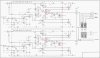
In attachment a picture with the final stage of MA6100
Sorry for my english pls !
I ask you to help me for a McIntosh MA6100. Recovered from a friend in a bad state.
There was a huge noise and he go in a safe mode after a few minutes. The final transistors were very hot. I just take some measurement in the supply voltages and compared with the schema, nothing was good. I don’t remember the values directly but I decided to directly change the large filter capacitors (10000 µ), the diodes and, the capacitors in parallel on each diode, in 42 V section (sorry I do not see the notations in the PDF that I have on my possession). Measured, voltages are ok.
Here comes the disaster. I just get out the final stages from the socket (dock?) for visual inspection and I put it back. I turn the amp and ….. boom. 4 fuses burn out. One false movement from my part? I don’t know. I paid attention but ....
I checked for short circuit, output to speaker…. nothing abnormal, the protection thyristors ok. But the result is quite heavy.
- Final transistors Q415-Q418 (open circuit). A substitute MJ21196G (better than MJ15003G? from what I have read on other forums)
- Pre-end transistors Q411 - Q414 dead (open circuit). Replace with 2N4923 / 2N4920 pairs
- The diodes D415 - D416 in the emitter of this transistors, dead’s. Replace with 1N4148 ?
- The resistor 10 ohm in the emiter have a value of 18 ohms. Bad?
- Transistors Q407 - Q410 dead (open circuit). Replace with MPSA06 / MPSA56 peers
- One of the two diodes fixed on the final transistors radiators D403 shorted. To be replaced by ...?
2 x 1N4148 in series (I've read on other forums)
- Resistors 0.33 ohms to the final transistors collectors in open circuit. Value: 0
- The diodes D413 - D413 simulated by GE PNP transistors (132-098) died (open circuit). Any substitute pls?
Open circuit = no conductivity, nothing measured, 0
What is happening I have no idea. Or the fact to restore the correct alimentations made it all started ....
If you could advise me for the replacements and any idea from you is welcome….. !!!!!!!!!!
Thank you very much you all.
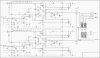
In attachment a picture with the final stage of MA6100