• The move to the new server is done. There are some software and database maintenance updates in process. This has us passing the hat around to help out. We appreciate any donations. Seriously, even a dollar helps. The payment page may be found here - https://www.audiokarma.org/support.html

mcintosh mac 1900 receiver driver board transistors numbers needed please help!

Yes this component is a germanium transistor it is written on it

View attachment 2866721

View attachment 2866722

But honestly , I don't think that this component is the reason of your problem

Are you sure to use the right ref transistor instead the original transistors obsolete ?

See my pictures , you have a good reference for using MPSA05 and MPSA55 instead the "yellow dot " transistor and "orange dot " transistors

If you get too much difficulties send me a PM I probably can help you

Did you ask availability to the factory ?

PATRICE
Making MCINTOSH repair since more than 40 years

Yes. I mean No! I do not think this diode/transistor is the problem. Mine has just a barely visible dot, no writing. It is just the only component that is out of parameters/faulty on the left output board. Last three times I have turned the power on, the resistors pictured in my post (mislabeled MAC 1900 output transistor replacement- Jon Weston) have burst into flame, so....I'm a little cautious. I want all the leads from the left board to read the same resistance as the right board, which does not catch on fire, before I try again. That one Germanium transistor on the left board is shorted, ...0.4...1.1ohms. The right output board, or D413, is about 80ohms. Current meeting no resistance, and rushing to the 10ohm resistor, is about as good an explanation for the flames as I can think of.

At least, realizing there is no resistance where a diode was expected makes me hesitant to turn it on one more time, so I'm looking for a transistor-that-can-be-made-into-a-diode which will give me the same 80ohms I get with the right channel board (all in-circuit, so where that 80ohms actually is I don't know)
 
OK try the last part number I have posted 070-xxx

I can't believe that the factory have no stock because I probably replace 3 pieces in more than 40 years so they schould have some (the factory)
 
Yes. I mean No! I do not think this diode/transistor is the problem. Mine has just a barely visible dot, no writing. It is just the only component that is out of parameters/faulty on the left output board. Last three times I have turned the power on, the resistors pictured in my post (mislabeled MAC 1900 output transistor replacement- Jon Weston) have burst into flame, so....I'm a little cautious. I want all the leads from the left board to read the same resistance as the right board, which does not catch on fire, before I try again. That one Germanium transistor on the left board is shorted, ...0.4...1.1ohms. The right output board, or D413, is about 80ohms. Current meeting no resistance, and rushing to the 10ohm resistor, is about as good an explanation for the flames as I can think of.

At least, realizing there is no resistance where a diode was expected makes me hesitant to turn it on one more time, so I'm looking for a transistor-that-can-be-made-into-a-diode which will give me the same 80ohms I get with the right channel board (all in-circuit, so where that 80ohms actually is I don't know)

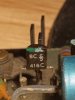
Sorry, to be complete with the last post, a stop-gap transistor diode, something that will allow me to turn on the amp, with no fire, and confirm that replacing 132-080, 132-081, and the two mj15003s on the left channel, all resistors that burned, and the two BL416Cs on the left board has solved the major problem I started with. Then I can wait with some peace of mind for two NOS replacement Germanium transistors to make my 1900 "all well".

Does that make any sense?
 
Another precious informations that you will find nowhere

Page with the commercial reference of this transistor orderable with a diode part number code and not under ref 132-xxxx

View attachment 2866723


and now an original drawing made by factory many many years ago


View attachment 2866724
Thank you. It may not be completely evident from my replies, but you are answering my questions fantastically. This is the knowledge which I was trying to find, reading about "common-source" amps, "common-gate" amps...all because of a mis-identification of the D414 transistor as = to 2N5345, or an n-channel JFET. That was as close as I could find to "connecting two transistor leads to make a defacto diode".

Your points are appreciated!
 
Thank you. It may not be completely evident from my replies, but you are answering my questions fantastically. This is the knowledge which I was trying to find, reading about "common-source" amps, "common-gate" amps...all because of a mis-identification of the D414 transistor as = to 2N5345, or an n-channel JFET. That was as close as I could find to "connecting two transistor leads to make a defacto diode".

Your points are appreciated!

I'm now shopping for identical replacements for D413, D414, and will resort to buying them from MAC, as you suggest, if all else fails.

JW
 
My mistake. I apologize. What I meant was BC416C as in the picture I attached here...View attachment 2866765
One of those, it seemed now 5+ years ago, was shorted, so by the time I picked it up again recently I had a board with both of those removed, and something as close as I could find back then replacing one of them. I have now replaced both. Various threads here have discussed the reliability of the originals (with the colored paint spots on top), newer but now obsolete versions of same, and alternatives....so I don't claim to know definitively that that was necessary and good, just couldn't find anyone who did, or didn't.
 
Sooo. I've found a Germanium transistor to replace the shorted one. Nothing lying around would come close to the working example on the other board. Because I'm for the most part stuck with in-circuit testing with a multimeter, it's hard to tell what the general situation is. Plug one hole, and re-check. Each faulty component replaced jigs the numbers more in line with the functioning board, but there's still a problem beyond the Germanium transistor/diode, I'm pretty sure.

As to what I think you were calling the reference transistors (black w/ orange and yellow dot)....they seem to be OK in comparison w/ the other board. The ohms resistance between BC and BE seems to be about 650 on one board, and 750 on the other. I assume that will change once the new Germanium transistor is in place, maybe eliminating the difference. We'll see.

Those (reference transistors) are about the last thing I haven"t thought of needing to replace yet. Curiously all of the electrolytic caps and other "usual suspects" seem fine through all of this. I did replace a 470pf ceramic disc cap with two 221s and a 30 in parallel for now.

Thanks again, clinic_audio!

Cross fingers...
 
Jon, I obtained a lifetime supply of the older Motorola and RCA germanium and silicone transistors. If you have a need and can't locate one give me the part number and I will look. I use silver mica to replace some of the ceramics on the driver boards. I'd be glad to help.
 
Jon, I obtained a lifetime supply of the older Motorola and RCA germanium and silicone transistors. If you have a need and can't locate one give me the part number and I will look. I use silver mica to replace some of the ceramics on the driver boards. I'd be glad to help.

Thanks, but I couldn't deal with another delivery/mail lap over that one transistor and found a higher end repair guy here in town who had some to spare. Somehow, either before I started catching things on fire, or in conjunction with that, the 132-079 PNP driver trans (the middle one) turned up shorted, as did three of the four .33 ohm cement resistors.... :-0... I used a salvaged B649 as a temporary 2N4920/MJ532?...132-079 by any name, and 3 salvaged .33 ohm 5 watt cement resistors, replaced the GE trans/diode, and.....it seems to hold it's electricity, no fire or smoke. No output except hum, though.

Next, I went at it with an external amp and headphones plugged into the front jack. I could trace both channels from output board to speaker wire terminals without any problem. Can't get anything from pre-amp boards to output boards.

I did, however, by turning it on with the DMM plugged into the main speaker terminals, get a very distinct ramping up, then falling off of the voltage indicative of a large, cycling (working) electrolytic cap. on each channel. So I checked the speaker fuses underneath. All good.

I'm going to pull the pre and output boards and check voltages on the power supply board (hum seems to be constant, both channels....)

Can't think of anything else to do....

Any ideas anyone??
 
Thanks, but I couldn't deal with another delivery/mail lap over that one transistor and found a higher end repair guy here in town who had some to spare. Somehow, either before I started catching things on fire, or in conjunction with that, the 132-079 PNP driver trans (the middle one) turned up shorted, as did three of the four .33 ohm cement resistors.... :-0... I used a salvaged B649 as a temporary 2N4920/MJ532?...132-079 by any name, and 3 salvaged .33 ohm 5 watt cement resistors, replaced the GE trans/diode, and.....it seems to hold it's electricity, no fire or smoke. No output except hum, though.

Next, I went at it with an external amp and headphones plugged into the front jack. I could trace both channels from output board to speaker wire terminals without any problem. Can't get anything from pre-amp boards to output boards.

I did, however, by turning it on with the DMM plugged into the main speaker terminals, get a very distinct ramping up, then falling off of the voltage indicative of a large, cycling (working) electrolytic cap. on each channel. So I checked the speaker fuses underneath. All good.

I'm going to pull the pre and output boards and check voltages on the power supply board (hum seems to be constant, both channels....)

Can't think of anything else to do....

Any ideas anyone??


What I meant was, by turning the power on, and off quickly, I could get what looked like a capacitor "filling up with volts", then spending long enough gliding back to zero once the power was cut, that the filter caps must be OK, only thing big enough to hold onto the juice that long.

Is that correct thinking? (I have no ESR to just check with)
 
Have now checked (many, diverse) voltages on the power supply card/board of this 1900 against service manual, this with the P.S. and both pre-amp cards plugged in. All within a volt or two of spec...??? No signal etc. makes it from pre-amp to output that I can find, but I'm hesitant to try and inject a signal or headphone lead into the guts with the power on. I think I'll try messing with the amp-in, pre-amp out jacks, since that's a physical bridge the signal must pass through, but don't have any ideas what to do. All the front lights etc. come on just fine. There are hints when switching from Tape-1 or AM FM, that all of that is working OK. I guess I could try hanging a wire AM antenna out the window of my 4th floor apartment, and see if that makes it out of the pre-amp.....?
 
OK, so I deoxit'd all the panel controls on my 1900, and attempted to signal trace my way through to the pre-amp from Tape Mon-1 or Tape Mon-2, but was all wore out somewhere in the middle of those Mode Selection buttons...

Is/was it just a question of saving redundant wire and space inside that led them to daisy chain all those buttons into the signal path? I swear I could not figure out the logic or pattern of which switch outputs and inputs were attached to what...at all at all. It definitely clarified how and why deoxit is suggested often in conjunction with a 1900 though

and replaced the tiny little diode on the reverse side of the left output board with a Germanium diode, which I've almost concluded was the problem that got the whole cascade of smoke and sparks I've been working through going. Since replacing that, neither the 5watt cement resistor, nor the 079 driver trans next to it even got warm. If that diode goes, becomes shorted, it seems to cause the middle driver trans (132-079) to just dump power continuously into the junction of the .33 ohm cement resistor, and one assumes on into the MJ15003s. Two more of which have replacements in the mail now.

I did, however, get an AM signal out of the right channel and speaker, fuzzy without a proper antenna, but there. The first evidence of anything before the output boards so far. One assumes, with the arrival of a few more replacement components already mentioned, that this mystery has been solved
 
Got all my 1900 output board replacement components and soldered them in. Double checked everything because, with all the confusion, repeated smoke and flames, though very brief, the back side of my left output board is not a a very pretty sight by now. Whatever old school solder was originally used....it does not mix well with the ROhS compliant stuff I've been using. I think there must be at least 100° f difference in the melting points of the two.

Anyway, all seemed....well enough. One driver transistor was giving 100K+ ohms off of one lead where no continuity/connection would be correct according to theory and comparing with the other board.

Fired it up and...turned it off real quick because, well, there are no light emmiting diodes on that board but there, indeed, was a diode emmiting quite a bit of light!! My goodness, the very same one I had just mentioned replacing in my last post.

AND SO I HAVE LOCATED AND CONFIRMED WHAT HAD BEEN THE PROBLEM ALL ALONG!!

This might, in fact, be of interest to the general MAC community (at least in pouring over related threads for weeks now, I've never heard anyone mention it)

Folks have noticed, noted, and posted confusion re:replacement transistors in depth, and width, but in case nobody has noticed, there is an actual typo in the schematics of the 1900 service manual:

The diode on the back side of the 1900 output boards, drawn with dotted lines running diagonally from the left lead of the middle driver transistor (132-079, the only PNP of the three, I think) to the proximate lead of the cement .33 ohm (bias?) resistor is clearly labeled "D414" or "D413"

But it is not!

D414 and D413 are actually the PNP Germanium metal can transistors made into diodes by twisting the B and C lead together. All of this is clearly labeled and diagramed about an inch or two to the left on the same schematic. (Thanks again to whoever explained all that to me when I needed to replace the "real D414")

If one considers carefully the parts list and schematics in the service manual, however, one will notice a D403 and D404 in the list that does not exist anywhere on the schematics.

One would also note that these diodes and only these diodes are spec'd as silicon diodes,that is to say NOT si. signal diodes or Germanium diodes etc., this being shorthand for "current diodes" or general purpose diodes, the only diodes spec'd as such anywhere in that neighborhood. So if you did as I had and tried to go by channeling the spirit of like items/components...you can keep doing laps around that circuit, putting in some other wispy signal or otherwise qualified diode, which will immediately fry, usually short, and dump 40v or -40v right into the MJ15003 output transistors, incinerating resistors along the way.

Fortunately I cut off the power quick enough this time to save one of MJ15003s on that side (I got a spare along with the replacements most recently, but only one)

In conclusion, that diode hiding on the solder side of MAC 1900 output boards is actually D404 or D403, and needs to be much beefier than any of the other D4XXs.

That's all I've got.

Thanks to everyone for advice given, which was needed and correct such as it was, along the way.

Jon W
 
This might, in fact, be of interest to the general MAC community (at least in pouring over related threads for weeks now, I've never heard anyone mention it)

Folks have noticed, noted, and posted confusion re:replacement transistors in depth, and width, but in case nobody has noticed, there is an actual typo in the schematics of the 1900 service manual:

The diode on the back side of the 1900 output boards, drawn with dotted lines running diagonally from the left lead of the middle driver transistor (132-079, the only PNP of the three, I think) to the proximate lead of the cement .33 ohm (bias?) resistor is clearly labeled "D414" or "D413"

But it is not!

D414 and D413 are actually the PNP Germanium metal can transistors made into diodes by twisting the B and C lead together. All of this is clearly labeled and diagramed about an inch or two to the left on the same schematic. (Thanks again to whoever explained all that to me when I needed to replace the "real D414")

If one considers carefully the parts list and schematics in the service manual, however, one will notice a D403 and D404 in the list that does not exist anywhere on the schematics.


In conclusion, that diode hiding on the solder side of MAC 1900 output boards is actually D404 or D403, and needs to be much beefier than any of the other D4XXs.

That's all I've got.

Thanks to everyone for advice given, which was needed and correct such as it was, along the way.

Jon W


Working from the 4X230 - AL9999 service manual, but in regards to D404 & D403, they appear throughout all of the service manuals available online.

In the middle working on a unit with 2 different board revisions, one missing the "rear diode", and stumbled across this thread. Thought I'd share what I've found.

D404 & D403 are attached to the heat sinks towards the bottom, and soldered to a standoff mounted near by. They can be seen in the schematic between pins 15 & 10. This is a stabilizer diode, P/N 070-046, which is the NLA MZ2361.

1790020577695.png

In regards to the "rear diode", the part number is incorrect both on the schematic, and the board view. It appears to have been forgotten all together when it came to the parts list, but I can confirm that it is actually P/N 070-047, which crosses to a 1N4148.

1790017555931.jpeg
 
Last edited:
Back
Top Bottom