I recently rebuilt power and bias circuits on MC30. The caps have been replaced. The 6L6GC grid is -44V but I'm reading -10V to -12V at the plate. So negative voltage in a spot where rectified B+ voltage should have been filtered from the power supply. This does not look, feel or sound good to me, but I'm hoping for someone to point out a simple knuckleheaded mistake I'm making? The inductors look fine and I've started going through the resistors. Most have been fine so far. There is no sound passing through the amp. All tubes have tested normal. The pins and sockets have been cleaned. I'm going to continue my way through the resistors, but wanted to put this out for questions, comments. Thank you all for your time and consideration.


You are using an out of date browser. It may not display this or other websites correctly.
You should upgrade or use an alternative browser.
You should upgrade or use an alternative browser.
McIntosh MC30 Plate Voltage Problem
- Thread starter J.T. Seal
- Start date
-
- Tags
- mcintosh vintage tube amp
Register to hide this ad

Kind of hard to see how that can be. To have -44 vdc on the output tube control grids, there must be plate voltage on the 12AX7 CF driver stage. But the 12AX7 driver gets its plate voltage from the plate winding of the OPT, so that means that the output tube screens (pin 4) must also have B+ present as well. The only way the output tube plates could not have B+ present then would be if both RF plate chokes were open — which would seem to be highly implausible. If there were no plate voltage on the 12AX7, then the 6L6 control grid voltage would be way too negative (assuming that the bias supply is operating correctly)— but the key to all of this, is that the output tube control grid voltage isn’t too negative, so something very strange in deed is going on.
Dave
Dave
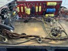
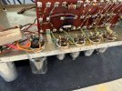
Thank you RJ!Pictures of your work please.
My thoughts as well!Kind of hard to see how that can be. To have -44 vdc on the output tube control grids, there must be plate voltage on the 12AX7 CF driver stage. But the 12AX7 driver gets its plate voltage from the plate winding of the OPT, so that means that the output tube screens (pin 4) must also have B+ present as well. The only way the output tube plates could not have B+ present then would be if both RF plate chokes were open — which would seem to be highly implausible. If there were no plate voltage on the 12AX7, then the 6L6 control grid voltage would be way too negative (assuming that the bias supply is operating correctly)— but the key to all of this, is that the output tube control grid voltage isn’t too negative, so something very strange in deed is going on.
Dave
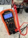
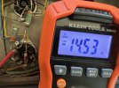

Last edited:
Thanks Dave! I think this unit partially melted down? The voltages are a little different this morning.Kind of hard to see how that can be. To have -44 vdc on the output tube control grids, there must be plate voltage on the 12AX7 CF driver stage. But the 12AX7 driver gets its plate voltage from the plate winding of the OPT, so that means that the output tube screens (pin 4) must also have B+ present as well. The only way the output tube plates could not have B+ present then would be if both RF plate chokes were open — which would seem to be highly implausible. If there were no plate voltage on the 12AX7, then the 6L6 control grid voltage would be way too negative (assuming that the bias supply is operating correctly)— but the key to all of this, is that the output tube control grid voltage isn’t too negative, so something very strange in deed is going on.
Dave
Last edited:
At what point in the circuit are the meter readings indicating?
Dave
Dave
Kind of hard to see how that can be. To have -44 vdc on the output tube control grids, there must be plate voltage on the 12AX7 CF driver stage. But the 12AX7 driver gets its plate voltage from the plate winding of the OPT, so that means that the output tube screens (pin 4) must also have B+ present as well. The only way the output tube plates could not have B+ present then would be if both RF plate chokes were open — which would seem to be highly implausible. If there were no plate voltage on the 12AX7, then the 6L6 control grid voltage would be way too negative (assuming that the bias supply is operating correctly)— but the key to all of this, is that the output tube control grid voltage isn’t too negative, so something very strange in deed is going on.
Dave
At what point in the circuit are the meter readings indicating?
Dave
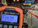
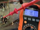
518 is taken between 10K10W resistor and 20mfd terminal of multi-section can cap. Let me get the right photos of plate and grid measurements from this morning. +14.38, +14.53 plates. -76.1, -72.7 Thanks again!At what point in the circuit are the meter readings indicating?
Dave
Thank you! Will recheck.To read plate voltage you should be on pin 3 on the octal sockets (where the RF chokes are soldered).
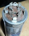
Looking at this can sitting on my bench, realized what this problem could be. Found similar on installed can, removed and seems to have resolved.To read plate voltage you should be on pin 3 on the octal sockets (where the RF chokes are soldered).

clinic-audio
all on YAMAHA untill 1990
Hello
did you made measurement on each capacitor value you should find in each section ?
did you made measurement on each capacitor value you should find in each section ?
Yes, they were very close to stated values. The 30 uF measured 28 uF.Hello
did you made measurement on each capacitor value you should find in each section ?