• The move to the new server is done. There are some software and database maintenance updates in process. This has us passing the hat around to help out. We appreciate any donations. Seriously, even a dollar helps. The payment page may be found here - https://www.audiokarma.org/support.html

MCS 3249 Phono Output Only One Channel

golfnut

Well-Known Member
The receiver output works great on both channels in aux, tape monitors, and FM. When I use the phono input, I only get sound out of one channel. It does not matter if I switch the rca cables on the turntable. The turntable has been tested on another receiver and works fine.

I have changed all 8 caps with no change.

My question(s) are:
Could a resistor(s) be the culprit? And I guess I could compare the good channel to the bad for comparison.

Also, this has IC chips, M5213L, would on of those be an issue? Also, and if so, would there be a good replacement for those?

Thanks for any advice.
 

Attachments

  • MCS3249 preamp board.jpg
    MCS3249 preamp board.jpg
    97.9 KB · Views: 11
Register to hide this ad
Not likely a resistor. Without seeing a schematic it is most likely an opamp or a transistor if the circuit is discreet. You need to trace the signal where it goes into that channel and see where it stops. Compare it with the working channel.
 
Not likely a resistor. Without seeing a schematic it is most likely an opamp or a transistor if the circuit is discreet. You need to trace the signal where it goes into that channel and see where it stops. Compare it with the working channel.
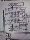
Thanks. I'm trying to determine if the M5213L IC is bad. However, the pin ID's on the board are not the same as the schematic. So, before I jump in, I wanted to know how I could test the IC.
 

Attachments

  • MCS3249 EQ Schematic.jpg
    MCS3249 EQ Schematic.jpg
    99.2 KB · Views: 19
  • MCS3249 EQ Board M5213L.jpg
    MCS3249 EQ Board M5213L.jpg
    74 KB · Views: 21
You cannot test the opamp per se. You need to check the signal going in and out.
Run a signal through it and check the pins on the opamp on each channel and compare. Get a copy of the datasheet for that opamp to see which pins do what.
Compare the inputs from channel to channel, then the outputs.
 
I can’t tell for sure without seeing the entire schematic but it looks like pins 2 and 6 are inputs/outputs. Do you have an oscilloscope? Signal/function generator?
 
You cannot test the opamp per se. You need to check the signal going in and out.
Run a signal through it and check the pins on the opamp on each channel and compare. Get a copy of the datasheet for that opamp to see which pins do what.
Compare the inputs from channel to channel, then the outputs.
Ok. Well I’ll have to do more reading on that. Thanks for getting back with me.

Would it likely be the IC that’s causing the one channel problem or something feeding into it?
 
Most likely the opamp, you said you already changed the capacitors. But that is why you check the signal going in and going out. If you have a good signal going in but not going out you found the problem. Troubleshooting 101.
Ideally with a signal generator and an oscilloscope.
 
Yes that is the opamp.
If you cannot adequately do the tests I suggested you can flip the opamps from left to right and right to left. If the one was bad the other channel will be the one that is out after flipping them.
 
Yes that is the opamp.
If you cannot adequately do the tests I suggested you can flip the opamps from left to right and right to left. If the one was bad the other channel will be the one that is out after flipping them.
Ok so with negative to chassis, I get the following readings on the M5213L:
Pin#/Schematic voltages/My readings
Left Channel (no phono audio output side)
1/21.4/20.6
2/0/-.01
3/0/-.28
4/-22.1/-21.8
5/0/-.39
6/0/-.23
7/22.1/21.7

Right Channel (audio works)
1/21.4/20.9
2/0/-.01
3/0/-.01
4/*22.1/-21.9
5/0/-.46
6/0/.02
7/22.1/21.8

Where is should be 0, I do have a small reading generally.
Are pins 1, 4, 7 on both channels close enough to be working properly?

I only changed the e-caps. There a several (16) brown (film) caps. Should I be able to compare them (L to R) in circuit?

I appreciate the help. Thanks
 
Measuring the DC voltages doesn’t tell you much about the problem. Like I said before you HAVE to trace a signal. You didn’t answer my question about what test equipment you have.

I don’t have a datasheet for that opamp in front of me to know if those voltages are a problem or not.

Pin 6 differences may be an issue.
 
Last edited:
Measuring the DC voltages doesn’t tell you much about the problem. Like I said before you HAVE to trace a signal. You didn’t answer my question about what test equipment you have.
Ok Sorry. I have a couple DMM's.

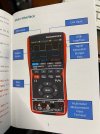
I have this Oscilloscope MM, but have never used that feature nor sure how to. I guess that is my homework.
 

Attachments

  • oscilloscpoe.jpg
    oscilloscpoe.jpg
    74.9 KB · Views: 3
  • oscilloscpoes.jpg
    oscilloscpoes.jpg
    61.1 KB · Views: 3
Ok so you don’t have a signal generator. Hook everything up and put on a record, preferably mono, that has a relatively constant sound level. Even static will work. Use the oscilloscope function or the AC voltage function to measure both opamps (this is assuming that it is sensitive enough to measure this) I think pins 2 and 6 are the input and output. Compare left and right. If the left opamp is bad the output will be 0 or A LOT lower than the right.

I
Looked it up, pin 2 is the input 6 is the output.

IMG_1757.jpeg
 
Last edited:
Ok so you don’t have a signal generator. Hook everything up and put on a record, preferably mono, that has a relatively constant sound level. Even static will work. Use the oscilloscope function or the AC voltage function to measure both opamps (this is assuming that it is sensitive enough to measure this) I think pins 2 and 6 are the input and output. Compare left and right. If the left opamp is bad the output will be 0 or A LOT lower than the right.

I
Looked it up, pin 2 is the input 6 is the output.

View attachment 3723873
Nice. So pin 2 on both channels are about the same at 6mv.
However, pin 6 on the good channel is well over a hundred at times where as pin 6 on the left is about the same 6mv.
So, that means the M5213L on the left channel is bad for the output...right? That makes sense. Thank you for this specific instruction on testing. I'm sure I'll have to find a substitute as this receiver was built in the 80's.
 
Were you measuring DC voltage or AC signal voltage?
If DC that difference could indicate a bad opamp but it doesn’t confirm it. Checking an AC signal at the in and out would.
 
Were you measuring DC voltage or AC signal voltage?
If DC that difference could indicate a bad opamp but it doesn’t confirm it. Checking an AC signal at the in and out would.
I checked again and there is a big difference between the two pin 6's.
 
Last edited:
Make sure that you are identifying Left and Right properly as an AC signal voltage “should” be lower in the bad channel. But it doesn’t have to be.

Were you feeding a signal in when measuring?
 
Yes I was feeding a signal via the turntable. I did not have a mono album, but the difference was great. I may switch the rca plugs at the same place on the record to confirm. The AC voltage was lower on the bad channel. It looks like there are replacements with 8 pins versus the 7. I also saw the M5213L on ebay.
 
Back
Top Bottom