• The move to the new server is done. There are some software and database maintenance updates in process. This has us passing the hat around to help out. We appreciate any donations. Seriously, even a dollar helps. The payment page may be found here - https://www.audiokarma.org/support.html

Meridian 557 Power Amp Issue

dilburt

New Member
I have a Meridian 557 that has been part of a Meridian stack I bought back in 1998 or so (502, 500, 566-24, 557). It's all performed flawlessly on a daily basis since last week when my 557 turned on then promptly turned itself back off. I removed all inputs and outputs and tested again with the same results. I haven't been able to find a Meridian audio expert in the Seattle area and the current factory rep which is a home theater showroom center didn't even know what a 557 was so I had the local MacIntosh guy (reluctantly) check it out. He was pretty impressed after taking the top off but said the bias on the right channel is high which he thinks is causing the protection to trigger. However, since it's an auto bias system and he doesn't have any schematics for this, he's gone as far as he can.

Has anyone seen this problem before and if so do you have any idea of the cause? I'm an EE/CS with a bit of analog knowledge so I would guess it's a bad cap due to the age. I have a 556 schematic but I'm not sure if the bias and protection circuits are the same as on a 557. If anyone has a 557 schematic it would be very helpful in getting this fixed. Any other information or suggestions would be appreciated.
 
Register to hide this ad
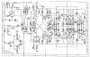
After doing some more troubleshooting, it appears the problem is a 250mV DC Offset that is causing the DC protection circuit to trip the protection relay on the relay board. If you look at page 1 of the attached 557 schematic (or the above 556 diagram which is the same except for device IDs), you will see "DC Protection" labeled under the bottom right LM339 op amp and if you follow to the left near the bottom left LM339 op amp you will see VA1111 - is this the DC offset adjustment? There are two 10uF electrolytic capacitors on the input side of the LM339 op amps and one on the input to the pnp drive transistor. If VA1111 is the DC offset adjustment, should I just tweak this to remove the 250mV offset or should I replace the three electrolytic caps first?

Thanks,

Dean
 
Something must have changed, very likely one or more capacitors aren't up to spec anymore.
I would replace them first. Do you have an ESR tester so you can check the capacitors?

VA111 looks to be related to DC offset and protect. Hoping someone else can chime in here.
 
I finally found the problem today and it wasn't anything I was expecting. I was probing around the inside of the case logging all the voltages and offsets and I poked the speaker connector (typical banana connector type) on the inside and voila, the amp powered up instead of shutting down. After staring dumbfounded at this for a while, I started inspecting all the speaker connectors and it turned out that by wiggling one of the + left channel connectors around I could make the amp fail or work. Apparently that connector must have a bad insulator that is allowing the + speaker side to ground against the chassis. I have ordered a new set of speaker connectors but have it working now and it's great to have this amp back. According to my ears, these are the sweetest sounding amps you can buy for under $3000.00.

Now onto the recapping project. I've ordered about half of what I need in Nickicon Gold Tune caps and am looking into a couple of other brands. Any opinions are welcome.
 
Capacitor selection is interesting. Here are some guidelines I use.
  1. Wima MKS II for 4.7uF to .47 uF
  2. Panasonic Polypropene or similar (ECFW) or Wima MKP for .33uf and below
  3. Nichicon UPW for Power Supply above 4.7uF
  4. Nichicon UKZ, UFG or Elna Silmic II for Audio path, i.e. not power related.
  5. For the main filter capacitors it can be tricky to find the right size, right specs, right lug/pin type etc so difficult to give a straight answer.

Polypropene is always better (1&2 above) however they are much larger and rarely fit. That's why you mainly see them used at .33uf and down other than crossovers.
You'll see real quick that a MKS2 4.7uf cap is a fraction of the size of a 4.7uf PP.
For the Panasonic Polypropene it seems the ECFWs are used, series seems to differ probably due to what voltage/value is needed.
 
Capacitor selection is interesting. Here are some guidelines I use.
  1. Wima MKS II for 4.7uF to .47 uF
  2. Panasonic Polypropene or similar (ECFW) or Wima MKP for .33uf and below
  3. Nichicon UPW for Power Supply above 4.7uF
  4. Nichicon UKZ, UFG or Elna Silmic II for Audio path, i.e. not power related.
  5. For the main filter capacitors it can be tricky to find the right size, right specs, right lug/pin type etc so difficult to give a straight answer.

Polypropene is always better (1&2 above) however they are much larger and rarely fit. That's why you mainly see them used at .33uf and down other than crossovers.
You'll see real quick that a MKS2 4.7uf cap is a fraction of the size of a 4.7uf PP.
For the Panasonic Polypropene it seems the ECFWs are used, series seems to differ probably due to what voltage/value is needed.

Thank you!

I have the 10uF 50v, 1000 uF 16 v and 1000 uF 63v caps in Nichicon Muse Fine Golds and am now looking for the audio path caps. Do you know anything about the big white cap that is connected to the relay board? On the schematic it just says "val" and the only reference for val for the relay board cap "15 uF for 110v, 10 uF for 240v" (it's bolted down & I haven't removed it to read the values yet). The values for c30 and c54 (the 2 largest caps on the circuit board) also just say "val" but they are labeled as Fine Gold 10,000 uF 80v. Also, there is a reference to c11 and c13 on the schematic as "val" but there are just empty places for them on the circuit board. They are filter/storage caps for V+ and V- at the bridge rectifier, any idea why they aren't being used?

Thanks,

Dean
 
The large ones (black with gold text, 10,000 uF/80V, Nichicon LKG) are the main filter capacitors. In the diagram they're called C11 and C13.
One of these three should work. But key here is diameter and height so the new ones fit physically. Also need to check how the lugs/pins look, can you take a photo from the underside of the board?
https://www.mouser.com/Nichicon/Pas...vqx?P=1z0wqs8Z1z0zlbmZ1yx4attZ1yx4atu&FS=True

Can you take a closeup of the text on the white ones?
 
The large ones (black with gold text, 10,000 uF/80V, Nichicon LKG) are the main filter capacitors. In the diagram they're called C11 and C13.
One of these three should work. But key here is diameter and height so the new ones fit physically. Also need to check how the lugs/pins look, can you take a photo from the underside of the board?
https://www.mouser.com/Nichicon/Pas...vqx?P=1z0wqs8Z1z0zlbmZ1yx4attZ1yx4atu&FS=True

Can you take a closeup of the text on the white ones?

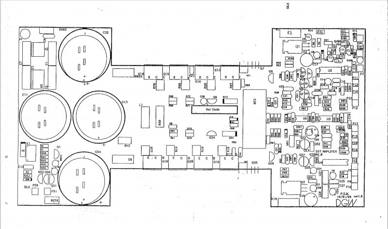
I don't have a photo since I haven't disassembled the amp yet but here is the official board diagram. The two in the middle labeled C11 & C13 are missing from all 557's I've seen so unless they are present on a few from the first production run, they probably were never used. Since C11 & C13 are between the bridge rectifier and the regulators they would typically be used to increase DC voltage under load and reduce ripple into the regulators. C32 & C54 are between the regulators and the power transistors so perhaps they decided the power transformer provided so much current and C32/C54 did such a good job of filtering that they weren't needed? I would love to hear if anyone knows why these were excluded. I can't think of any downside of including them other than cost factors (and air circulation but these run very cool) so I'll probably just buy an extra set of the 10,000uF/80v caps and add them when I recap.


Attachments

  • Screenshot Amplifier Board 2021-04-14 203541.jpg
    Screenshot Amplifier Board 2021-04-14 203541.jpg
    103.3 KB · Views: 4
Not sure what you mean by C11 & C13 missing.
They're the big black with gold text ones in the bottom middle of this picture.
Wasn't this from your amp?
upload_2021-3-26_22-26-18.png
 
Not sure what you mean by C11 & C13 missing.
They're the big black with gold text ones in the bottom middle of this picture.
Wasn't this from your amp?
View attachment 2195301

If you look at the board diagram above you will see there are 4 circles and connection holes for big caps but they have only populated 2 of these locations with capacitors - C32 and C54. The other 2 circles are for C11 and C13 but they do not have any capacitors installed in those locations. What I mean is that they are completely traced and connected on the circuit board, they are just missing from the board.

Regarding the picture, I screwed up. That is a picture of a project someone did with their 557 and I accidentally posted it instead of the correct picture. Here is the right one. You can see C54 and C32 at the top right and left. If C11 and C13 were installed you would see them below those caps and a bit towards the front and rear:

Stock 557 Amp.jpg
 
Last edited:
Well C32 and C54 is probably enough for the filtering. I agree, might as well install C11 and C13 but of course those caps typically cost some money.
Which one is the white one in the middle? Must be a big one as well.
 
Well C32 and C54 is probably enough for the filtering. I agree, might as well install C11 and C13 but of course those caps typically cost some money.
Which one is the white one in the middle? Must be a big one as well.

That is a motor start capacitor connected across the hot AC input and the relay output that kicks in after the "power good" signal a couple of seconds after the power switch is turned on. These are used in motor applications to shift the AC phase which causes a brief high current input to the windings to start the motor rotating. The way it's wired in the 557 connects one input to AC in and leaves the other input disconnected until the power good signal is kicked in then the other side is connected to the AC output which I think is used to stop high voltage transients and perhaps to do some magic with the huge toroidal power transformer during the first few cycles of AC. I'm not familiar with this application of these caps and would love to hear an explanation from someone who understands this.
 
That is a motor start capacitor connected across the hot AC input and the relay output that kicks in after the "power good" signal a couple of seconds after the power switch is turned on. These are used in motor applications to shift the AC phase which causes a brief high current input to the windings to start the motor rotating. The way it's wired in the 557 connects one input to AC in and leaves the other input disconnected until the power good signal is kicked in then the other side is connected to the AC output which I think is used to stop high voltage transients and perhaps to do some magic with the huge toroidal power transformer during the first few cycles of AC. I'm not familiar with this application of these caps and would love to hear an explanation from someone who understands this.

I meant what's the component ID?
 
Unfortunately, I haven't been able to find that. If you look at the schematic for the relay board there is a reference on the left that says: p4 p5 To Capacitor and then handwritten says "110v Relay / 15uF Cap, 240v Relay / 10uF Cap"

The other confusing part of the 557 schematics are that the pin numbers and other references from the relay board schematic do not line up with the AC input references on page 1 of the power amp schematic which is the only place where power input, bridge rectifiers and related components are shown so there is nothing about that cap there either. On the PCB layout for the relay board someone has handwritten a cap connection but based on the physical connections I see on the relay board, that is not drawn correctly.

Hope this helps...
 
Back
Top Bottom