• The move to the new server is done. There are some software and database maintenance updates in process. This has us passing the hat around to help out. We appreciate any donations. Seriously, even a dollar helps. The payment page may be found here - https://www.audiokarma.org/support.html

Minimus 7 Loudspeakers - Measurements

Thanks Pete,
That's very kind of you to say. Very much appreciate what you have done here for us as the P in the PZ.

I did refoam my 7's woofers - I wonder if the new foams substantially changed the Fs?

Have you tried running just an Impedance sweep?
 
Absolutely, that is step one of getting T&S from DATS which is a two step process. First you run the impedance sweep, then you add the mass and measure the Vas.

From the user manual:
a) Click on the "Measure Free Air Parameters" button at the left of the DATS V2 window. You should hear the sweep and then see the impedance response plotted on screen similar to Figure 1. The impedance magnitude is shown as a blue plot with the phase response shown in red. Several of the speaker's free air parameters are displayed in the Parameters Bar at the right side of the screen. The bar at the left side on the window is where you set the impedance and frequency limits for the current display.

DATS.png

b) Measure the driver's Vas. Once you have measured the speaker's free air parameters the "Measure V(as)" button becomes enabled. Select one of the four methods to measure the Vas at the upper right side of the DATS V2 screen.

 
Absolutely, that is step one of getting T&S from DATS which is a two step process. First you run the impedance sweep, then you add the mass and measure the Vas.

From the user manual:
a) Click on the "Measure Free Air Parameters" button at the left of the DATS V2 window. You should hear the sweep and then see the impedance response plotted on screen similar to Figure 1. The impedance magnitude is shown as a blue plot with the phase response shown in red. Several of the speaker's free air parameters are displayed in the Parameters Bar at the right side of the screen. The bar at the left side on the window is where you set the impedance and frequency limits for the current display.

View attachment 1746193

b) Measure the driver's Vas. Once you have measured the speaker's free air parameters the "Measure V(as)" button becomes enabled. Select one of the four methods to measure the Vas at the upper right side of the DATS V2 screen.


In that example above the Fs reads 66 Hz.,....Which sounds quite close obviously.

The post I mentioned a few days ago, showed the Minimus 7's woofer, at 128 Hz, that is what caused the confusion....

https://audiokarma.org/forums/index...ers-measurements.199790/page-43#post-13063270

Minimus 7 (40-2030B) T&S Workbench Notes:
f(s) = 128.5 Hz
Q(ts) = 0.5605
V(as) = 1.774 liters (0.06264 cubic feet)
SPL = 88.66 dB SPL 1W/1m
R(e) = 6.123 Ohms
Q(es) = 0.7927
Piston Diam. = 85 mm (3.346 in.)
SPL = 89.82 dB SPL 2.83 Vrms
C(ms) = 0.392 mm/N
L(e) = 1.292 mH at 1kHz
Q(ms) = 1.913
BL = 4.938
n(0) = 0.453 %
M(ms) = 3.909 grams

Enclosure volume = 1.8L gross
 
Yes I remeasured both of my minimus woofers and reconfirmed they both have an fs north of 100hz. See the attached pdf reports I attached there. The Teac that are similar have the lower 60hz fs which is the chart in the quote you are referring to if I'm not mistaken..
 
Replacement foam surrounds are available for the 77's. Check on Ebay, seller is bootapest2. I've refoamed a couple pairs using these surrounds and they work well.
Thanks for the info! I ordered a set, they got here in a couple of days. I used Aleene's Tacky Glue, the surrounds fit great and the glue easy to use, and dries clear. Very pleased with the results!!
 
Great thread! Thx @PeteB & Zilch (RIP) for the Minimus 7 mod & research.

Finally got around to performing the mod & went with drilling the back panel, using the #4-40 machine screws to hold the 1.0 Erse as Zilch suggested. Everything fits neat 'n tidy, used glue to hold everything down. Is it critical to use a wire nut for the Erse 1.0, (+) woofer wire, & 3ohm resistor connection? Or, to solder that specific 3 pt. junction?

My pair had different insulation installed, one w/ white polyfill, the other w/ yellow FG. Was thinking about swapping both w/ pink FG insulation. Any recommendations as to which insulation?

Looking thru the thread @Pete B mentions briefly in #98 but am a little confused about packing the insulation,...no insulation behind the woofer? So far, one speaker has more bass (yellow fiberglass) the other (white poly-fill) seems brighter to my ears & bass is not as 'present'.
 
Solder is better, then position it so it does not short to anything or put a wire
nut over it. Soldering is gas tight and will last forever.

I'd guess that more likely one woofer is slightly different from the other, but
sure use whatever fiberglass you have and stuff as you did the other one,
just to rule it out.
 
^^Thank you.^^

The 7s do sound good after the mod. Was listening to some Diana Krall, 'When I Look Into Your Eyes,' with an HK 330C for testing & the sound-stage is present. Separation is quite lovely actually. Pretty amazed at these little guys.
 
Has anyone tried the PZ2.1 mod on the Optimus Pro77?

My understanding is the Pro77 is pretty much the same as the Minimus 77 except with the port?

I just picked up a pair of Pro77's for $10 at Goodwill with rotten surrounds. Just finished re-foaming with inverted surrounds from seller bootapest2 on eBay. They are sold as Minimus 77 surrounds, but they fit the Optimus Pro 77's very nicely.

note: his add specifically states they won't fit the Minimus Pro77. Not sure what the difference is between the Optimus and Minimus Pro77's (boy this gets confusing fast!).

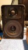
Anyway, they sound nice and I verified the crossover looks to be the exact same as the stock Minimus 7 with a 4.7uf in series to the tweet and a 0.4mH inductor in parallel. The woofer is run full range. Tweeter looks to be the same tweeter too. Bass is definitely deeper and the surrounds aren't even broken in yet. Thought these would make nice bench speakers, but now thinking if the PZ2.1 crossover works as good on these as it does on the 7's that these might make nice bedroom speakers.

20200703_205803.jpg
 
Has anyone tried the PZ2.1 mod on the Optimus Pro77?

Thought these would make nice bench speakers, but now thinking if the PZ2.1 crossover works as good on these as it does on the 7's that these might make nice bedroom speakers.
A bit earlier in this thread, ericj reports having done the mod on Pro-77's:
I've performed this mod on a pair of 7's, a pair of 7W's, and a pair of Optimus Pro-77's (which are a bit too boomy and this is maybe not an ideal xover for them)

There may be others, though can't recall at the moment.
 
I'm willing to bet they are identical and the crossover mod will be great.

The crossover doesn't affect the woofer level, it does attenuate the tweeter. The port acts to extend the very lowest bass output only and doesn't affect the midrange where the crossover operates.

Give it a try, what have you got to lose?

If the bass is too boomy move them away from the wall or plug the port.

Good luck!
 
I am having a great deal of difficulty finding the actual modifications in this 894-post thread.

Can someone distill this down into what exactly is done, step-by-step? I have three pair I'd like to convert. I saw the link in the OP, but the images are broken and is useless for me.
Thanks.
 
I am having a great deal of difficulty finding the actual modifications in this 894-post thread.

Can someone distill this down into what exactly is done, step-by-step? I have three pair I'd like to convert. I saw the link in the OP, but the images are broken and is useless for me.
Thanks.

Read post #691. It has the bill of materials and the schematic.

As for the step-by-step, buy the parts, remove the original crossover, and install the new parts. You can use point-to-point wiring to make the crossover.

PS: Read the thread. There is a lot of good info contained herein, even though it takes a while to get through it.
 
I am having a great deal of difficulty finding the actual modifications in this 894-post thread.

Can someone distill this down into what exactly is done, step-by-step? I have three pair I'd like to convert. I saw the link in the OP, but the images are broken and is useless for me.
Thanks.

Summary here: https://audiokarma.org/forums/index...ers-measurements.199790/page-43#post-13260161

Also see the posts after #854:
https://audiokarma.org/forums/index...ers-measurements.199790/page-43#post-13260259
 
A question on the 0.4 uH inductor: I bought the Dayton air core listed as optional on the parts list. It’s 0.4 ohms while the original is 1.0. Is it indeed better to use the lower-R inductor since I have it (other than taking up a bit of volume)?

Thanks!
 
Back
Top Bottom