


Kahoona
Super Member
Hi
This is an amp that I bought in the late 70's/ early 80's and used for 10 or 20 years. I recently got it back and want to make it work well again. It played when I got it back but the bias and offset were way out of whack. I had planned on doing a minor repair but it looks like at lease a recap is a better idea. I have the solder skills and equipment but don't know what makes things work exactly. I can repopulate a board but troubleshooting can be hard. I am learning though. Before I begin swapping parts en mass I would like to find out where the actual problem lies. The good part is that the Bias is set-able and solid on both sides. I replaced the trims for the bias before I set it. The problem is that the offset cannot be set on the right side. The trims do not seem to have any effect. The left can be set but is unstable. I am guessing there is a problem n the right side.
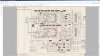
I have a German Service Manual which I can not understand much of. The schematic is good though. What it does not have is the voltages for the test spots on the board. Does anyone have these? Here is what I get
Left-
#8- Orange wire +59v
#6- Orange +5.8v
#11- Gray 4v
#13- Blue -58v
#15-Brn +4.7v
#10- Grn +4.7v
Right-
#38- Orange -58v
#36- Yellow +.7v
#41- Gray **
#43- Blue -58v
#45- Brn **
#40 Grn **
** indicates a variable reading of less than a volt that I am assuming to be 0.
I am guessing that I have a problem with 45 and 40 and I can start checking things near them on the schematic.
Here is the schematic

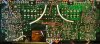
And a shot of the board which should be vert large but I am not sure how big it will come through.

The board has been cleaned up a bit since it was taken. The funny spot where the board is notched is a repaired crack. It only passed through one trace so I bridged it with wire, soldered it to the trace. The crack ends at a hole so won't get longer. I repaired the physical crack with super glue then with Bondic. I love Bondic!!
I just uncovered a schematic with voltages on it. It is for the DA-A10 which is a similar amp but it may help.

I will get to checking voltages and seeing what I can deduce. Please let me know if you have any suggestions.
Stay tuned and I will post plenty of pics.
Thanks
This is an amp that I bought in the late 70's/ early 80's and used for 10 or 20 years. I recently got it back and want to make it work well again. It played when I got it back but the bias and offset were way out of whack. I had planned on doing a minor repair but it looks like at lease a recap is a better idea. I have the solder skills and equipment but don't know what makes things work exactly. I can repopulate a board but troubleshooting can be hard. I am learning though. Before I begin swapping parts en mass I would like to find out where the actual problem lies. The good part is that the Bias is set-able and solid on both sides. I replaced the trims for the bias before I set it. The problem is that the offset cannot be set on the right side. The trims do not seem to have any effect. The left can be set but is unstable. I am guessing there is a problem n the right side.
I have a German Service Manual which I can not understand much of. The schematic is good though. What it does not have is the voltages for the test spots on the board. Does anyone have these? Here is what I get
Left-
#8- Orange wire +59v
#6- Orange +5.8v
#11- Gray 4v
#13- Blue -58v
#15-Brn +4.7v
#10- Grn +4.7v
Right-
#38- Orange -58v
#36- Yellow +.7v
#41- Gray **
#43- Blue -58v
#45- Brn **
#40 Grn **
** indicates a variable reading of less than a volt that I am assuming to be 0.
I am guessing that I have a problem with 45 and 40 and I can start checking things near them on the schematic.
Here is the schematic

And a shot of the board which should be vert large but I am not sure how big it will come through.

The board has been cleaned up a bit since it was taken. The funny spot where the board is notched is a repaired crack. It only passed through one trace so I bridged it with wire, soldered it to the trace. The crack ends at a hole so won't get longer. I repaired the physical crack with super glue then with Bondic. I love Bondic!!
I just uncovered a schematic with voltages on it. It is for the DA-A10 which is a similar amp but it may help.

I will get to checking voltages and seeing what I can deduce. Please let me know if you have any suggestions.
Stay tuned and I will post plenty of pics.
Thanks

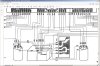

 . There are voltages on there too but no notice of which pin. Would it be easier to read if I added it in quarters for better Resolution?


