• The move to the new server is done. There are some software and database maintenance updates in process. This has us passing the hat around to help out. We appreciate any donations. Seriously, even a dollar helps. The payment page may be found here - https://www.audiokarma.org/support.html

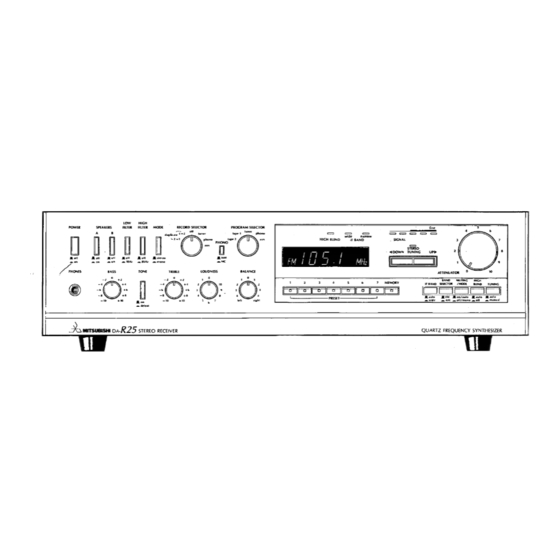
Mitsubishi DA-R15: Diagnostic Project

PattonD

Member
IMG_0573.jpeg

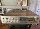
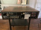
I bought this DA-R15 for $30. According to the previous owner, it was functioning perfectly fine until a turntable was connected; it hasn't produced sound since. It’s now on my bench as a testbed for learning how to diagnose, and hopefully repair. That sounded like a protection circuit so I took a flyer, if for no other reason to use as a learning platform.

I found the owners manual, but not a schematic, I think it’s the same as HiFi Engine’s but don’t have access to check. Anyone have a link? The is a schematic on eBay for $55, this unit isn’t worth that investment.

I’m learning as I go here so any tips, watch outs ar best practice diagnostic steps common on these receivers would be appreciated
 

Attachments

  • IMG_0578.jpeg
    IMG_0578.jpeg
    171.6 KB · Views: 9
Register to hide this ad
There is no service manual at HiFi Engine. It is the owner manual. Try looking for a different model from the same series. Maybe it will be close enough to guide you.
 
Analog Alley shows they have a service manual for the DA-R15 available. I got one for my DA-R7 from there. Not free, but not too bad either. I think I paid $15 for mine. I’ve gotten several. Top quality scans in every case. No affiliation, just a satisfied customer. Btw, I’m enjoying this humble DA-R7 quite a bit.
IMG_1725.jpeg
Cheers………………Todd
 
Thank you, I appreciate that
Analog Alley shows they have a service manual for the DA-R15 available. I got one for my DA-R7 from there. Not free, but not too bad either. I think I paid $15 for mine. I’ve gotten several. Top quality scans in every case. No affiliation, just a satisfied customer. Btw, I’m enjoying this humble DA-R7 quite a bit.
View attachment 3744672
Cheers………………Todd
i saw they have the DA-A15, I'll send them a note on the DA-R15

Thanks
 
Yeah, you have to email Norman with a request. It’s listed in the archive but not yet the store. That means it’ll take them a day or two to get it scanned and processed. It was the same for my DA-R7.
Cheers………………..Todd
 
Suggest unplug the item then lift the lid and have a look inside for any damaged/stressed components, you wont see any but it's good practice. Also note if it has a protection relay also if it has STK type power amp stage or conventional transistors.

Do you see any test points/pins/posts in the vacinity of the output transistors, possibly used for bias. Also near the output transistors should be 4 large white (emitter) resistors. You could try measuring the dc voltage from any leg of any emitter resistor and chassis/GND, black speaker connector are almost always at GND so handy clip on point. The voltage will be close to the dc offset, should be less than 50mV, more than 300mV would typically trip protection.

Worthwhile to build a dim bulb tester (DBT), numerous plans on AK, it's a current limiting device for first power up after repair.

A health check of the power supply is one of the first things that should be done, however without a schematic it's a bit hard to explain, basically looking for symmetry on the +ve and -ve rails of regulated and unregulated supplies

If you suspect the amp is in protection measure Vdc at emitter resistors will confirm. At some point you should diode test the output transistors, nice graphic from markthefixer
 

Attachments

  • DiodeTest.JPG
    DiodeTest.JPG
    38.9 KB · Views: 9
Thanks, @mbz . That looks like a solid diagnostic path and exactly what I was looking for to get started. I've noted the steps and the advice is very helpful.

I am just getting my bench setup and I actually finished building my DBT yesterday, so I’m set on that front. I’ll start by getting the cover off to see what I'm working with and check those basic voltage points to see if it's actually stuck in protection mode.

I’ll post some photos of the internals once I have it on the bench.
 
  • Like
Reactions: mbz
I’ll post some photos of the internals once I have it on the bench.

I *think* this model uses STK "power packs" and a 15-pin "voltage amplifier" to compose all the active parts of the power amps, so you might want to note exactly what part numbers are in your example.
 
Yeah, you have to email Norman with a request. It’s listed in the archive but not yet the store. That means it’ll take them a day or two to get it scanned and processed. It was the same for my DA-R7.
Cheers………………..Todd
It’s been a few weeks and I haven’t heard back from Norman, does it usually take him a while to reply.
 
It’s been a few weeks and I haven’t heard back from Norman, does it usually take him a while to reply.
That's weird! No, for me it's been like next business day. So, how did you contact him? I'm 99% sure I just emailed Analog alley directly at 'analog alley at gmail dot com'. all one word. I did not use any of the contact forms on the website. (There are a couple different ones I've seen) Good luck!
Todd.
 
I must have had user issues with the form, because Norman replied right back to my email. He is going to scan in the manual for me and will have it for me and a couple of days.
 
Good to hear! I need to order one for my Bang & Olufsen RX2 turntable. One suggestion - and maybe you do this already - but I always take the PDF to my local Kinkos (Fed Ex store) on a thumb drive and get the busier pages like the schematic and PCB diagram printed on large format (18" x 24") paper. That makes them a lot easier to read for me.
Cheers..............................Todd
 
Took the DA-R15 to the local makerspace and got it on an electronics bench with an experienced member of the space to try and diagnose tonight.

Signal chain: IC501 STK3042 MK2 drives two downstream STK1050s (IC502/IC602).

Found clean signal on IC501 pins 1 and 15. Both L and R output legs showing sawtooth oscillation, visually identical. That carries into both STK1050s, whose output doesn’t respond to volume or input changes. STK1050s appear to be passing what they receive, not independently failed.

Prior tech addressed the F-line service bulletin, C508/C608 replaced, evidence of rework on the STK1050 pin rows. IC501 and surrounding caps appear untouched.

Proposed fix: replace IC501 STK3042 MK2 (if a can source a real one) and all surrounding capacitors.

Learned a lot about following a schematic and using a multimeter and scope to try and isolate an issue. Does this hold up? Any experience with STK3042 MK2 oscillation appreciated.
 
Back
Top Bottom