


I finally got around to recapping the ML-1C speakers. Here is how the experience went for me. I rebuilt the crossover of one speaker and put my family through some blind tests by sending a mono signal through one speaker and then another. They all said the rebuilt speaker sounded better. As for my impression – the speakers were slightly veiled before the recap. They sounded better to me after the work. It was not a drastic change. I really enjoyed the sound of the speakers to begin with and worried that I would loose the character of the speakers, but this was not the case. Just a little more detail and clarity. Well worth it!
I used the service manual to get a parts list together.
I ordered the caps, resistors, and caulk from Parts express (no affiliation). Cap and resistor choices are personal – this is just a guide and a timesaver.
All the resistors were of this type (only one value included in link) except one value that was not available for which I subbed in a more generic wire wound I had in stock.
Dayton Audio DPR10-6.0 6 Ohm 10 Watt Precision 1% Audio Grade Resistor
The speakers must be airtight when they are reassembled and this calk worked well.
Parts Express 12" Speaker Sealing Caulk Box of 72 Pcs.
For the parallel cap I ordered this bi-polar cap
150uF 100V Electrolytic Non-Polarized Crossover Capacitor
The rest of the caps needed were of this type. (only one value included in link)
Dayton Audio PMPC-1.0 1.0uF 250V Precision Audio Capacitor
The speakers were laid on their back using two short boards underneath to avoid putting pressure on the banana jacks. Remove the 12” woofer and unplug the wires from it.
Remove the fiberglass (use gloves) and set it aside in a way that makes it easy to put it back in the same orientation when you finish. Remove the wires and screws holding the crossover and then bring it to your soldering area.
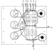
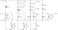
There are some differences between older and newer iterations of these classic speakers. If you do not have the newest version of the crossover. It is recommended that you update to the final version. Very early versions had only four coils – recommended that you find a coil to update. Some of the resistors also changed value. The schematic and layout included here are the final version that should be followed. R6 on my speakers was the 64Ohm 5W from note #4. That was the only older revision in my crossovers. I replaced with the 56Ohm 10W from the final revision.
Solder in the new parts. Glue down the caps and resistors. I put toothpics under the resistors and glued them to the main plate and the resistors to the toothpics so there would be some room for airflow around the resistors. Use the caulk to seal the 12” speaker and the crossover – it must be air tight.
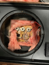
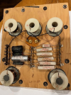
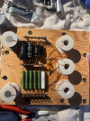
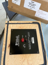
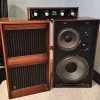
I have included pictures as I wished I could find some before I opened my speakers. I like to know what to expect before I start. Hopefully this post helps the next guy. Pretty cool that the date was stamped onto the crossover! OCT 18 1971.
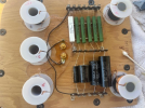
I also took time to use contact cleaner on all the wire connectors and posts, and took pains to clean off all the flux.
The speakers should be good for another 50+ years.
I used the service manual to get a parts list together.
I ordered the caps, resistors, and caulk from Parts express (no affiliation). Cap and resistor choices are personal – this is just a guide and a timesaver.
All the resistors were of this type (only one value included in link) except one value that was not available for which I subbed in a more generic wire wound I had in stock.
Dayton Audio DPR10-6.0 6 Ohm 10 Watt Precision 1% Audio Grade Resistor
The speakers must be airtight when they are reassembled and this calk worked well.
Parts Express 12" Speaker Sealing Caulk Box of 72 Pcs.
For the parallel cap I ordered this bi-polar cap
150uF 100V Electrolytic Non-Polarized Crossover Capacitor
The rest of the caps needed were of this type. (only one value included in link)
Dayton Audio PMPC-1.0 1.0uF 250V Precision Audio Capacitor
The speakers were laid on their back using two short boards underneath to avoid putting pressure on the banana jacks. Remove the 12” woofer and unplug the wires from it.
Remove the fiberglass (use gloves) and set it aside in a way that makes it easy to put it back in the same orientation when you finish. Remove the wires and screws holding the crossover and then bring it to your soldering area.
There are some differences between older and newer iterations of these classic speakers. If you do not have the newest version of the crossover. It is recommended that you update to the final version. Very early versions had only four coils – recommended that you find a coil to update. Some of the resistors also changed value. The schematic and layout included here are the final version that should be followed. R6 on my speakers was the 64Ohm 5W from note #4. That was the only older revision in my crossovers. I replaced with the 56Ohm 10W from the final revision.
Solder in the new parts. Glue down the caps and resistors. I put toothpics under the resistors and glued them to the main plate and the resistors to the toothpics so there would be some room for airflow around the resistors. Use the caulk to seal the 12” speaker and the crossover – it must be air tight.
I have included pictures as I wished I could find some before I opened my speakers. I like to know what to expect before I start. Hopefully this post helps the next guy. Pretty cool that the date was stamped onto the crossover! OCT 18 1971.
Oh yeah –
I used E6000 Craft Industrial Strength Clear All Purpose Adhesive to glue down the components. This was suggested on several crossover posts here on AK and it really worked well. It stays 'rubbery' which I think adds some vibration protection.I also took time to use contact cleaner on all the wire connectors and posts, and took pains to clean off all the flux.
The speakers should be good for another 50+ years.


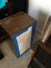



![IMG_1999[1].JPG](/forums/data/attachments/3323/3323049-f434766a8255d3a618a6d02ab8c53ac2.jpg?hash=9DR2aoJV06)

![IMG_2002[1].JPG](/forums/data/attachments/3323/3323968-8a55eabf91d24331a60f77b37eb401e9.jpg?hash=ilXqv5HSQz)
