• The move to the new server is done. There are some software and database maintenance updates in process. This has us passing the hat around to help out. We appreciate any donations. Seriously, even a dollar helps. The payment page may be found here - https://www.audiokarma.org/support.html

Model 1200 - bias doesn't go above 0mV

ocdecio

The proof of the restoring is in the listening.
Subscriber
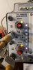
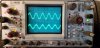
I just finished rebuilding the left amplifier channel of a 1200. I checked voltages connected to a DBT, and they all seem to be pretty close. Light dims, and when I connect it to a signal generator I get a clear, amplified wave in the output. DC is close to 0mv.

However no matter what I do I can't get a bias above 0.00mv across R531 and R532, when I should be looking at 12mv ideally. I know I am connected to the DBT but I expected at least something.

I checked the epoxy transistor, it seems OK with a hFE of 500. The germanium 1N542 diode is brand new.

I am at a loss. What could be preventing it from getting a bias?

upload_2021-4-17_11-2-31.png

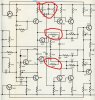
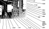
Voltages: at (4) +0.6V; (5) -0.595V

upload_2021-4-17_11-22-38.png
 

Attachments

  • 20210417_093541.jpg
    20210417_093541.jpg
    62.2 KB · Views: 11
  • 20210417_093532.jpg
    20210417_093532.jpg
    90 KB · Views: 11
Last edited:
Register to hide this ad
Do you get a reading on the right channel while on the DBT? Usually if the DBT goes dim you're done with the DBT.

Craig
 
Do you get a reading on the right channel while on the DBT? Usually if the DBT goes dim you're done with the DBT.

Craig
Hi Craig,

I get 2mv on the right channel with the DBT.

-Otavio
 
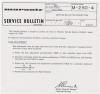
Full disclosure - I modified the Left channel following the service bulletin and the following components were added:


R557
C520

R522 and R523 at the driver's emmiters.

I wonder if that is related to the bias trimpot R526 being downgraded from 1k to 250ohm - it just so happens these are impossible to find.


Screenshot 2021-04-17 134155.jpg
 
Another thing I noticed... in the schematic the points between R531 and R532 that are usually the ones to measure across to get
bias are explicitly set to 0V (please look at the Q510/Q511 driver emmiters) :

If that is to be the case, where and how should bias be measured now?


upload_2021-4-17_13-52-41.png
 
Reading with interest - I have a 1200b that I picked up late last year that is working it's way to the bench.
The 1200B should be easier to work with, if it is the one with the upright pots and two transistors in the bias circuit. It resembles the 240 a lot. What serial number is yours?
 
Serial number is 9815.
I see that the VRs are much easier to access due to their orientation.
Passed DBT and on full power I'm getting ~150mv at the speaker terminals. I haven't dug into the manual too deeply, but bias and offset instructions are not jumping out for me.
I don't want to hijack this thread at all, but can you point me in the right direction for test points and specs?
 
@vmedia DC you should be able to adjust the pot at the edge of the board - you should try getting as close to 0mv as possible - I wouldn't connect a speaker with 150mv. If you can't get DC to go down, you have an issue that may need investigating.

As for bias, open the sides exposing the output transistors. You should get from 12 to 15mv between the center two cases. Be extra careful not to short anything while measuring! You also will want to check after warming up and adjust as needed. That would be in the pot at the center of the board. Be very careful here - these are really wirewound rheostats and it is very easy for them to go out of whack with a slight movement due to age. I would consider deoxiting it and exercising it a bit to get all the crud out before attempting to adjust bias. Same procedure for the other pots.
 
Thank you for the info! Agreed - no speakers getting hooked up any time soon.
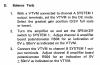
Looks like the manual details the Bias procedure under the heading of "balance tests."
R504 (VR) provides the adjustment
 
Thank you again - I wasn't processing that the 1200b's amp is basically a 250 - I will get all documentation and do my homework.

Also, I used the wrong term in my last post? Bias is set using VR526...DC Offset is VR504?
 
Well - that explains why I couldn't find VR504 on the board layout...I think the manual may have a typo? If the "balance adjustment" is the proper procedure for measuring DC at the speaker terminals?
 

Attachments

  • Screen Shot 2021-04-24 at 8.20.50 AM.png
    Screen Shot 2021-04-24 at 8.20.50 AM.png
    328.6 KB · Views: 15
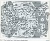
Must have been a typo. Here's a picture of a board just like yours.
upload_2021-4-24_11-27-34.png
 
Any advise on cleaning 502?
I was able to set the offset close to zero, but seems like every time I turn the unit on the offset is + or - 50mv.
Thinking step one is to more thoroughly clean the 502 - I've given a couple de-oxit treatments and I can tell that they are "crunchy". Most of what I have read seems to point to a thorough cleaning vs replacement.
 
This generation, at least on the 250's, had several revisions of amp boards. The manual only shows one. Fun, huh?!
 
Any advise on cleaning 502?
I was able to set the offset close to zero, but seems like every time I turn the unit on the offset is + or - 50mv.
Thinking step one is to more thoroughly clean the 502 - I've given a couple de-oxit treatments and I can tell that they are "crunchy". Most of what I have read seems to point to a thorough cleaning vs replacement.
The crunchy ones may have wire wound elements so feel that way normally.
 
Back
Top Bottom