• The move to the new server is done. There are some software and database maintenance updates in process. This has us passing the hat around to help out. We appreciate any donations. Seriously, even a dollar helps. The payment page may be found here - https://www.audiokarma.org/support.html

Model 19 Cap List

Velox

Just a bug hunt, Ripley..
Does anyone have a Marantz Model 19 recap list? Or transistor, diode, resistor etc list? Parts you have used that you recommend? I have reviewed the forum Model 19 threads but cannot find any summary list. I did contact one of the rebuilder experts for the 19 on this board, but he replied that he does not give out cap lists. Thank you for any info!
 
Register to hide this ad
I had to do some more work on my Marantz 19 so I thought I would post my mods here. I was having 2 issues:
1. a low level hum on all functions, with the volume at minimum.
2. A turn on pop.
I had already completely recapped the receiver so I ended up increasing the values on some of the filter caps. The hum was coming from the preamp stage and the power supply is a very simple design with only a zener diode shunt regulator, so I had to increase the capacitance values as shown on the schematic in the link below. The original multisection caps are no longer available so I used single caps and I had to install several jumpers to complete the ground paths that were provided by the case of the original multisection caps. It is important to install the jumpers in the photo below or you will not get good enough ground paths and you will get hum. Use a thick copper braid or solder wick.
For the turn on pop I had to remove C1404 on the delay board, which is a "select at test." The original value was 10uF but it caused the delay to not work because the voltage at pin 1403 came up after the voltage at pin 1402, so it didn't keep the front end of the amp turned off as the power supply came up, causing a pop. I suspect C1404 isn't going to be needed in most receivers. With the mods the hum is gone and there is no turn on or turn off thump.
https://drive.google.com/file/d/1zUbwP7CcbwX3djxk-e1B2a4wMbMSaNH1/view?usp=sharing
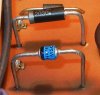
C1404 is at the North end of the board:
5HaWGysoRDCV-H3JcZTxq3p18bpVbp7At0tP0Haiz1KNkZ3SqZBNzsjmtkCJd-nfQMOBETttyWpdNnfPY4h_KRACXjvva19h7M0eImh12vRUdjSmmVRN7yNbuEaB17yLIdgNyQru6jOb3_a3ue_XwE20opGaTx_MjTIniL0GxzP3mjbDrmEl0YkIS6mHpvvNRvyURoO_9otr5OqbDw-wo7qAtyIiSPjdZAx_BUhlsXl9yUSc-9Hca6ZOoFJj2okjAJy_ACC2kUnybjiaMAP7RgXZL1TCXq_BThpEf7qbATpEiMFKmbCsKvPRmYX4KJ2mpc3T0X6_Uxc-MrE6GN3yn1YPwVeDjKGtuW4ka9iqkCI6EtfLZeQWHkw4bxhad1UyKt7xgUe0nQMN0MbsU_u0DVPtCzFZ4WHvg2IcZg4YY8KCnrUzmI0uIBriYUP4xvVkgbTzsVTwf9xTqFt7kxbyskMA4vF3upTs7Rw9K3unk42ML-9mDo5991cNPqnsHDjroVTCcd-gNsAJSQyi3ipYccVhuj3hJNrVPWCW07JBQs2LDCk7m5c4IkTocLmxe_-2ii_6Bx4des8tPCDQ3SDhRTWyZfIpQ2LE-OfriiE_2hF5xIQ__qcTrFjV2t_GM3vZ3VqsE5-nOGCErceWq9Z4zYVgOLuPWDU=w1242-h931-no

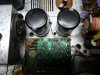
Power Supply Caps:
gfJilg1Osp7KvbtjOOyiGovo89ZbYSh5JL6VHVc9Mev2FsA0WZ41OKdYyjew-k4Zu4WMjwl0iNtc3fbWAK10axnS7RWQCPvWCSuKP3M3HYZkh0grbi-RmwOqMMjRZlSAyHFPeuQNaYHTZpt4nXn8xQhJ8oxLHeA4o37X0XaoN2XOBjejWlda5PfqIxjVitrtIhRyVfK95WKNY9W5NcUESYugZPUd2xWhtHZvmE8OtClVpxuYyICTx3mvFNNtvQmw-Z5EbMiSlZJi4eimplwWHTfrzOhS1GpxvFOMlYkMg4Qz6CRCn8SHVU-zXT7YotpSGxZC4Z0D4Lx0er7EC03kpDnF7YeZpyX4rrLiV8Mg9t1Pp4cpEqVPekZYsWNKo4LH4t9YLxVirIqK9vK3uWA94qOf7JcBDZQmSyXtxVNbTamsIp6l8spRpTFoIf92Utkmv47cvMGXgHnwqiIyDlKOT4A_-WF2NeC7hTIDUTduP4KL2QYhK-UBtWNOCEaIz04gt4xJoZ9Bqz1auRa3H1y3W360_BFSZjWHGBgBnkaPA82qR6igExIyxMQGmdlMpTFCCmw8r7WVEpTclFh0ZVQWsiGide1-HbVANqPlOuWPCqF-JG8DVF6g7yrJkvkrpmRcCwPaWk1BtNH3oM8GRzdwP9gND1QbTkY=w1242-h931-no

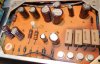
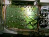
Bottom side of the Power Supply Board, showing polarity markings and jumpers. Note that I had to add a jumper from the board to the ground at the main caps, so now there are 2 of them:

4EtKUnpV1u_oi5soizWwY_TGAsgqP8Ij6Y2ZAX7WCoQcNjoYuVmNKPHyujVr2Nv3C_eiSrDgexrfD77KN8X7YyoeteaWYqygTnNbD-DXF7AbK5tjgg4XjOXac0vpadJ5f-miHQUUB2L0ZIGx4cnZ8mx6ObZEHPFgTA738g2MI1q2w34x6w4mscgnpUIyWrsTbvMcrPIgsGD6KRAmbPXflvfB_J4HrnXYOoJd-2e5smXqma-RTl3uAiDTj9u_WAwVcipjJRYPBhKTt3TeyaO0LlPq0lRVZv0bVx0KHWjjPFdzlolDkij-x8Jqisj7ecDtLJd4HX4aZC6d_3GI3a-IuJe1swmzcQ1Z5qraXkjrTzjeuYpu-WY5Z6W_JtLTZvb_0SgTHCgB0ekWwl1-jhDFZvwooSD-DD3Fzt7ck4GG1OtNLjHyQs3TBl7107XFO4r7rnoLxFpUnAhiPeVq2vqwl1kGdw4zCLg5Ma2Sx7zjolTAyYKDA6RlI82wzpQY-TxhOb1ekyBNwWpIaYvSBZ-Z_ik_R6o3tYUHx_HHvcfcunFnzCUoOkhq4e7i6IWNRL7bDC7yPTpt8HJjLzKN25KmH07QnmB77UD5KbnWJowfYlCMZUUNrRMVrlbko8yu_wlFjc80QclZra3AufvSybQkU6bzPgaROSY=w1242-h931-no
 
Looks like the images are gone, could you upload them again, please?


I had to do some more work on my Marantz 19 so I thought I would post my mods here. I was having 2 issues:
1. a low level hum on all functions, with the volume at minimum.
2. A turn on pop.
I had already completely recapped the receiver so I ended up increasing the values on some of the filter caps. The hum was coming from the preamp stage and the power supply is a very simple design with only a zener diode shunt regulator, so I had to increase the capacitance values as shown on the schematic in the link below. The original multisection caps are no longer available so I used single caps and I had to install several jumpers to complete the ground paths that were provided by the case of the original multisection caps. It is important to install the jumpers in the photo below or you will not get good enough ground paths and you will get hum. Use a thick copper braid or solder wick.
For the turn on pop I had to remove C1404 on the delay board, which is a "select at test." The original value was 10uF but it caused the delay to not work because the voltage at pin 1403 came up after the voltage at pin 1402, so it didn't keep the front end of the amp turned off as the power supply came up, causing a pop. I suspect C1404 isn't going to be needed in most receivers. With the mods the hum is gone and there is no turn on or turn off thump.
https://drive.google.com/file/d/1zUbwP7CcbwX3djxk-e1B2a4wMbMSaNH1/view?usp=sharing
C1404 is at the North end of the board:
5HaWGysoRDCV-H3JcZTxq3p18bpVbp7At0tP0Haiz1KNkZ3SqZBNzsjmtkCJd-nfQMOBETttyWpdNnfPY4h_KRACXjvva19h7M0eImh12vRUdjSmmVRN7yNbuEaB17yLIdgNyQru6jOb3_a3ue_XwE20opGaTx_MjTIniL0GxzP3mjbDrmEl0YkIS6mHpvvNRvyURoO_9otr5OqbDw-wo7qAtyIiSPjdZAx_BUhlsXl9yUSc-9Hca6ZOoFJj2okjAJy_ACC2kUnybjiaMAP7RgXZL1TCXq_BThpEf7qbATpEiMFKmbCsKvPRmYX4KJ2mpc3T0X6_Uxc-MrE6GN3yn1YPwVeDjKGtuW4ka9iqkCI6EtfLZeQWHkw4bxhad1UyKt7xgUe0nQMN0MbsU_u0DVPtCzFZ4WHvg2IcZg4YY8KCnrUzmI0uIBriYUP4xvVkgbTzsVTwf9xTqFt7kxbyskMA4vF3upTs7Rw9K3unk42ML-9mDo5991cNPqnsHDjroVTCcd-gNsAJSQyi3ipYccVhuj3hJNrVPWCW07JBQs2LDCk7m5c4IkTocLmxe_-2ii_6Bx4des8tPCDQ3SDhRTWyZfIpQ2LE-OfriiE_2hF5xIQ__qcTrFjV2t_GM3vZ3VqsE5-nOGCErceWq9Z4zYVgOLuPWDU=w1242-h931-no

Power Supply Caps:
gfJilg1Osp7KvbtjOOyiGovo89ZbYSh5JL6VHVc9Mev2FsA0WZ41OKdYyjew-k4Zu4WMjwl0iNtc3fbWAK10axnS7RWQCPvWCSuKP3M3HYZkh0grbi-RmwOqMMjRZlSAyHFPeuQNaYHTZpt4nXn8xQhJ8oxLHeA4o37X0XaoN2XOBjejWlda5PfqIxjVitrtIhRyVfK95WKNY9W5NcUESYugZPUd2xWhtHZvmE8OtClVpxuYyICTx3mvFNNtvQmw-Z5EbMiSlZJi4eimplwWHTfrzOhS1GpxvFOMlYkMg4Qz6CRCn8SHVU-zXT7YotpSGxZC4Z0D4Lx0er7EC03kpDnF7YeZpyX4rrLiV8Mg9t1Pp4cpEqVPekZYsWNKo4LH4t9YLxVirIqK9vK3uWA94qOf7JcBDZQmSyXtxVNbTamsIp6l8spRpTFoIf92Utkmv47cvMGXgHnwqiIyDlKOT4A_-WF2NeC7hTIDUTduP4KL2QYhK-UBtWNOCEaIz04gt4xJoZ9Bqz1auRa3H1y3W360_BFSZjWHGBgBnkaPA82qR6igExIyxMQGmdlMpTFCCmw8r7WVEpTclFh0ZVQWsiGide1-HbVANqPlOuWPCqF-JG8DVF6g7yrJkvkrpmRcCwPaWk1BtNH3oM8GRzdwP9gND1QbTkY=w1242-h931-no

Bottom side of the Power Supply Board, showing polarity markings and jumpers. Note that I had to add a jumper from the board to the ground at the main caps, so now there are 2 of them:
4EtKUnpV1u_oi5soizWwY_TGAsgqP8Ij6Y2ZAX7WCoQcNjoYuVmNKPHyujVr2Nv3C_eiSrDgexrfD77KN8X7YyoeteaWYqygTnNbD-DXF7AbK5tjgg4XjOXac0vpadJ5f-miHQUUB2L0ZIGx4cnZ8mx6ObZEHPFgTA738g2MI1q2w34x6w4mscgnpUIyWrsTbvMcrPIgsGD6KRAmbPXflvfB_J4HrnXYOoJd-2e5smXqma-RTl3uAiDTj9u_WAwVcipjJRYPBhKTt3TeyaO0LlPq0lRVZv0bVx0KHWjjPFdzlolDkij-x8Jqisj7ecDtLJd4HX4aZC6d_3GI3a-IuJe1swmzcQ1Z5qraXkjrTzjeuYpu-WY5Z6W_JtLTZvb_0SgTHCgB0ekWwl1-jhDFZvwooSD-DD3Fzt7ck4GG1OtNLjHyQs3TBl7107XFO4r7rnoLxFpUnAhiPeVq2vqwl1kGdw4zCLg5Ma2Sx7zjolTAyYKDA6RlI82wzpQY-TxhOb1ekyBNwWpIaYvSBZ-Z_ik_R6o3tYUHx_HHvcfcunFnzCUoOkhq4e7i6IWNRL7bDC7yPTpt8HJjLzKN25KmH07QnmB77UD5KbnWJowfYlCMZUUNrRMVrlbko8yu_wlFjc80QclZra3AufvSybQkU6bzPgaROSY=w1242-h931-no
 
I had to do some more work on my Marantz 19 so I thought I would post my mods here. I was having 2 issues:
1. a low level hum on all functions, with the volume at minimum.
2. A turn on pop.
I had already completely recapped the receiver so I ended up increasing the values on some of the filter caps. The hum was coming from the preamp stage and the power supply is a very simple design with only a zener diode shunt regulator, so I had to increase the capacitance values as shown on the schematic in the link below. The original multisection caps are no longer available so I used single caps and I had to install several jumpers to complete the ground paths that were provided by the case of the original multisection caps. It is important to install the jumpers in the photo below or you will not get good enough ground paths and you will get hum. Use a thick copper braid or solder wick.
For the turn on pop I had to remove C1404 on the delay board, which is a "select at test." The original value was 10uF but it caused the delay to not work because the voltage at pin 1403 came up after the voltage at pin 1402, so it didn't keep the front end of the amp turned off as the power supply came up, causing a pop. I suspect C1404 isn't going to be needed in most receivers. With the mods the hum is gone and there is no turn on or turn off thump.
https://drive.google.com/file/d/1zUbwP7CcbwX3djxk-e1B2a4wMbMSaNH1/view?usp=sharing
C1404 is at the North end of the board:
5HaWGysoRDCV-H3JcZTxq3p18bpVbp7At0tP0Haiz1KNkZ3SqZBNzsjmtkCJd-nfQMOBETttyWpdNnfPY4h_KRACXjvva19h7M0eImh12vRUdjSmmVRN7yNbuEaB17yLIdgNyQru6jOb3_a3ue_XwE20opGaTx_MjTIniL0GxzP3mjbDrmEl0YkIS6mHpvvNRvyURoO_9otr5OqbDw-wo7qAtyIiSPjdZAx_BUhlsXl9yUSc-9Hca6ZOoFJj2okjAJy_ACC2kUnybjiaMAP7RgXZL1TCXq_BThpEf7qbATpEiMFKmbCsKvPRmYX4KJ2mpc3T0X6_Uxc-MrE6GN3yn1YPwVeDjKGtuW4ka9iqkCI6EtfLZeQWHkw4bxhad1UyKt7xgUe0nQMN0MbsU_u0DVPtCzFZ4WHvg2IcZg4YY8KCnrUzmI0uIBriYUP4xvVkgbTzsVTwf9xTqFt7kxbyskMA4vF3upTs7Rw9K3unk42ML-9mDo5991cNPqnsHDjroVTCcd-gNsAJSQyi3ipYccVhuj3hJNrVPWCW07JBQs2LDCk7m5c4IkTocLmxe_-2ii_6Bx4des8tPCDQ3SDhRTWyZfIpQ2LE-OfriiE_2hF5xIQ__qcTrFjV2t_GM3vZ3VqsE5-nOGCErceWq9Z4zYVgOLuPWDU=w1242-h931-no

Power Supply Caps:
gfJilg1Osp7KvbtjOOyiGovo89ZbYSh5JL6VHVc9Mev2FsA0WZ41OKdYyjew-k4Zu4WMjwl0iNtc3fbWAK10axnS7RWQCPvWCSuKP3M3HYZkh0grbi-RmwOqMMjRZlSAyHFPeuQNaYHTZpt4nXn8xQhJ8oxLHeA4o37X0XaoN2XOBjejWlda5PfqIxjVitrtIhRyVfK95WKNY9W5NcUESYugZPUd2xWhtHZvmE8OtClVpxuYyICTx3mvFNNtvQmw-Z5EbMiSlZJi4eimplwWHTfrzOhS1GpxvFOMlYkMg4Qz6CRCn8SHVU-zXT7YotpSGxZC4Z0D4Lx0er7EC03kpDnF7YeZpyX4rrLiV8Mg9t1Pp4cpEqVPekZYsWNKo4LH4t9YLxVirIqK9vK3uWA94qOf7JcBDZQmSyXtxVNbTamsIp6l8spRpTFoIf92Utkmv47cvMGXgHnwqiIyDlKOT4A_-WF2NeC7hTIDUTduP4KL2QYhK-UBtWNOCEaIz04gt4xJoZ9Bqz1auRa3H1y3W360_BFSZjWHGBgBnkaPA82qR6igExIyxMQGmdlMpTFCCmw8r7WVEpTclFh0ZVQWsiGide1-HbVANqPlOuWPCqF-JG8DVF6g7yrJkvkrpmRcCwPaWk1BtNH3oM8GRzdwP9gND1QbTkY=w1242-h931-no

Bottom side of the Power Supply Board, showing polarity markings and jumpers. Note that I had to add a jumper from the board to the ground at the main caps, so now there are 2 of them:
4EtKUnpV1u_oi5soizWwY_TGAsgqP8Ij6Y2ZAX7WCoQcNjoYuVmNKPHyujVr2Nv3C_eiSrDgexrfD77KN8X7YyoeteaWYqygTnNbD-DXF7AbK5tjgg4XjOXac0vpadJ5f-miHQUUB2L0ZIGx4cnZ8mx6ObZEHPFgTA738g2MI1q2w34x6w4mscgnpUIyWrsTbvMcrPIgsGD6KRAmbPXflvfB_J4HrnXYOoJd-2e5smXqma-RTl3uAiDTj9u_WAwVcipjJRYPBhKTt3TeyaO0LlPq0lRVZv0bVx0KHWjjPFdzlolDkij-x8Jqisj7ecDtLJd4HX4aZC6d_3GI3a-IuJe1swmzcQ1Z5qraXkjrTzjeuYpu-WY5Z6W_JtLTZvb_0SgTHCgB0ekWwl1-jhDFZvwooSD-DD3Fzt7ck4GG1OtNLjHyQs3TBl7107XFO4r7rnoLxFpUnAhiPeVq2vqwl1kGdw4zCLg5Ma2Sx7zjolTAyYKDA6RlI82wzpQY-TxhOb1ekyBNwWpIaYvSBZ-Z_ik_R6o3tYUHx_HHvcfcunFnzCUoOkhq4e7i6IWNRL7bDC7yPTpt8HJjLzKN25KmH07QnmB77UD5KbnWJowfYlCMZUUNrRMVrlbko8yu_wlFjc80QclZra3AufvSybQkU6bzPgaROSY=w1242-h931-no

Hi
do you still have these photos? The website link doesn’t show the grounding jumpers either.
Thanks
 
Dang it, just did one a month or so ago and didn't take a picture of the jumpers! The old cans had 4 case common tabs but at one spot didn't use all four to make connection. Using the old holes for best natural fit left one or more new caps' common pins floating. You'll see that when you start installing the new parts. I can't recall which side it was on the caps, "+" or "-". By the way, be aware that some of the cans have the case common as the "+" side!
 
I’m really appreciative of the pictures y’all.

when I get done I can’t wait to hear that rewarding “click” of the relay.
 
Well, I hope you don't! The relay only clicks if there's an issue, the audio is normally connected through the contacts and if the protection is tripped it will click on and so disconnect the amps' output.
 
Well, I hope you don't! The relay only clicks if there's an issue, the audio is normally connected through the contacts and if the protection is tripped it will click on and so disconnect the amps' output.
Ok well the majority of my amps click when the relay receives the correct voltage
 
I was also going to ask if you all took your amp through all the audio section adjustments in the manual after completing the restores. I don’t have a distortion analyzer.
 
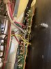
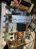
I ended up re-stuffing the cans. In retrospect, I’m m not sure I would do it again. The cans run fairly hot. I should have probably drilled a ventilation hole at top of can. However, it runs fine and sounds great. I just set dc off set and idle current when done with restoration.
E33B9B0C-1406-4F90-8C83-43BC4220F8A1.jpeg 389370E4-FE02-4C99-A89F-BCD96FE9CB03.jpeg 934CC406-3CB0-4289-8115-F20778F8EF09.jpeg
 
I ended up re-stuffing the cans. In retrospect, I’m m not sure I would do it again. The cans run fairly hot. I should have probably drilled a ventilation hole at top of can. However, it runs fine and sounds great. I just set dc off set and idle current when done with restoration.
View attachment 2223034 View attachment 2223035 View attachment 2223036

good to know. I started out with audio only in one channel. Probably a diode or trim pot from what I’ve read but I have a few resistors that have overheated on the driver boards.
 
Figure I’d post some updates. Missing the dgp30 rectifier on the power supply. One on eBay for $40 or I can wait for mouser to ship mine September 9th but in my experience these dates have been known to push out and out.
 

Attachments

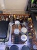
  • 150869FE-5AF4-4540-BD7B-507B83F727BC.jpeg
    150869FE-5AF4-4540-BD7B-507B83F727BC.jpeg
    149.8 KB · Views: 54
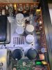
  • CFB14D92-1EC9-4A31-A69F-3047319C1E33.jpeg
    CFB14D92-1EC9-4A31-A69F-3047319C1E33.jpeg
    121.3 KB · Views: 53
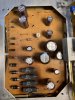
  • 02147D24-229F-450A-8EDC-757B92D329DE.jpeg
    02147D24-229F-450A-8EDC-757B92D329DE.jpeg
    142.6 KB · Views: 51
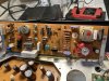
  • 60255530-581B-4752-856A-A848EFBDAB81.jpeg
    60255530-581B-4752-856A-A848EFBDAB81.jpeg
    110.3 KB · Views: 47
  • AE54C5F7-AA5F-4C2F-BE1A-8D416D5A67FB.jpeg
    AE54C5F7-AA5F-4C2F-BE1A-8D416D5A67FB.jpeg
    161.6 KB · Views: 54
Nice work! I see you left the silicone sealant out that goes on the board under the CRT. I would not recommend that. I don't think it is to hold the wires in place. That's the Phono input switch underneath, and the CRT has electrostatic deflection. There may be high voltage present on the outside of the CRT and I believe the silicone is to prevent arcing to the board. Could damage the phono preamp. I think what I did on mine was instead of silicone glopping up the area I put some insulating fish paper on the board, held in place with double sided tape.
 
Nice work! I see you left the silicone sealant out that goes on the board under the CRT. I would not recommend that. I don't think it is to hold the wires in place. That's the Phono input switch underneath, and the CRT has electrostatic deflection. There may be high voltage present on the outside of the CRT and I believe the silicone is to prevent arcing to the board. Could damage the phono preamp. I think what I did on mine was instead of silicone glopping up the area I put some insulating fish paper on the board, held in place with double sided tape.

thanks I’ll take your advice
 
does anyone have a actual value list of the caps they used in the power supply i see awsome pics but no cap list of what the values used were anyway i would love that information ythanks in advance i love the model 19 Mark....
 
does anyone have a actual value list of the caps they used in the power supply i see awsome pics but no cap list of what the values used were anyway i would love that information ythanks in advance i love the model 19 Mark....
I will take a look. But I literally just went down service manual and got the values from there. I verified with each cap as I removed from board. If I did find my list, it would not be anything special. Just hand written notes from the service manual. But I’ll take a look.
 
Back
Top Bottom