• The move to the new server is done. There are some software and database maintenance updates in process. This has us passing the hat around to help out. We appreciate any donations. Seriously, even a dollar helps. The payment page may be found here - https://www.audiokarma.org/support.html

Model 19 - I think I took a wrong turn....

Jamie Starr

Active Member
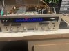
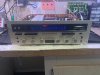
Hi guys. I picked up a Model 19 some time ago and decided to replace caps in selected locations, i.e. power supply, tone board, and driver board. Took my time and did board by board checking after each installation. The unit would work after each board installation, and I would move on.

During this time, I landed my first scope and signal generator as I enjoy the hobby and am trying to learn more. After the Model 19 was all recapped and working, I put on the scope. I noticed that the RIGHT channel would have distortion at about half volume, but only when the balance was to the right. Otherwise, no distortion on the scope.

So I started looking at the driver board. I hit RIGHT transistor Q1208 with freeze spray, distortion gone on scope when balance knob to the right. I am feeling pretty good about myself and after doing some research on AK, ordered a replacement.

Unfortunately, when I got the replacement and installed it, the LEFT channel would stop working???? I put reinstalled original part, and BOTH channels work, with original distortion when balance to right. I assumed I ordered the wrong part....but was confused as to why it would kill the output in the LEFT channel.

After trying 3 different replacement transistors that all appear to be acceptable replacements, the same thing would happen. No LEFT output.

After this, I decided to just to again reinstall the original part, and call it a day. BUT the electronic gods had a different idea. Now the LEFT channel ONLY works when the unit is plugged into the dim bulb tester or the variac is at about 90 volts and it is a distorted output. Otherwise no output.

The RIGHT channel plays but completely distorted.

So, I would take any advice about to to troubleshoot this. I have a clean sine wave going into both driver boards. From there, the sound does not make it out. The frustrating part is that nearly every component I have checked tests good. I have tested the output transistors and transistors on the driver board with my DCA 55. No shorts or leakage.

I am not sure what else I should be looking for? Could a bad resistor or diode cause something like this? I thank you in advance for any suggestions or plan you might suggest.
 
Register to hide this ad
I just looked at the Model 19 SM, found here on AK:
http://akdatabase.com/AKview/albums/Marantz/Marantz Model_19.pdf

VARXy30.jpg


On page 41, they detail how to adjust the Driver board. I have never seen a more thorough step by step in any of the other manuals for these procedures. The thing that stuck out most is they recommend using an 8 ohm load across the Speaker terminals, before measuring with a scope, which I've not seen in any of the other Marantz Solid State manuals. The way I have always understood it, you have to use a speaker or dummy load with a tube amp, but not with Solid State.

Wish I could be of more help. The only thing I can recommend would be to measure the stock Q1208 with your DCA 55, see if the pin-out and hfe match your replacements. If you can tell us what kind of transistor Q1208 was, and what your replacement is, that might help get this solved too.
 
Last edited:
I just looked at the Model 19 SM, found here on AK:
http://akdatabase.com/AKview/albums/Marantz/Marantz Model_19.pdf

VARXy30.jpg


On page 41, they detail how to adjust the Driver board. I have never seen a more thorough step by step in any of the other manuals for these procedures. The thing that stuck out most is they recommend using an 8 ohm load across the Speaker terminals, before measuring with a scope, which I've not seen in any of the other Marantz Solid State manuals. The way I have always understood it, you have to use a speaker or dummy load with a tube amp, but not with Solid State.

Wish I could be of more help. The only thing I can recommend would be to measure the stock Q1208 with your DCA 55, see if the pin-out and hfe match your replacements. If you can tell us what kind of transistor Q1208 was, and what your replacement is, that might help get this solved too.

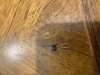
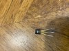
Thank you for the response. The original Q 1208 resistor appears to be a Motorola. The part number as MPSA56. The part is fairly easy to find at Mouser and other suppliers under the same part number. However, when received and installed, it did not work, and the LEFT channel would go dead. Another AK’r that has posted about a Model 19’s before suggested I use 2N3906 and that he has used that replacement with no issues. That one unfortunately did not work either. Here are some photos of the original part.

818F428C-6E4F-4733-A438-8AE2396F90B3.jpeg 97C496B2-971D-4938-89BD-8F88981A0A6C.jpegCF796864-C270-4607-918E-8DC1C4C8DAB8.jpeg 5612B6F3-8C4E-4F65-B552-51F2B1F4E0AB.jpeg
Below is a MPSA 56 part number I purchased as replacement.
BD16A631-5315-4D46-AE3B-DE2B4C83C2C4.jpeg 44565F66-B860-4600-B0E8-2B4763C7650F.jpeg
These are 2N3906.
7EBEDB8E-5851-4C97-8903-1C812C7897A2.jpeg 5BF90DFD-F642-45F1-A20B-1B56BEE2C91F.jpeg

All have the same pin out. Thanks again for taking the time to look at this and make suggestions.
 
Last edited:
Now the LEFT channel ONLY works when the unit is plugged into the dim bulb tester or the variac is at about 90 volts and it is a distorted output. Otherwise no output.

The RIGHT channel plays but completely distorted.

Is your Idle Current/Bias set correctly? Are you able to take measurements at full power, 120V?

Page 17:
WfeSBWx.jpg


R8wsQGe.jpg
 
Last edited:
Hello
Do you have the complete service manual for model 19 ?

Do you have this :

View attachment 1985805
Thanks guys for all the help. I do have a clean copy of the service manual. I do not recall where I left of with setting bias. Once the channels began cutting out and distorting, I got caught up in trying to locate a faulty component. I will go back and see where the amp is bias wise after work.

Question: Am I reading step 2 correctly. No input. Set volume at zero or lowest level AND POWER OFF amp? So set bias while the amp is turned off? Is that how you understand this procedure? Will my DMM even show a reading with the power amp off? Thanks again.
 
Is your Idle Current/Bias set correctly? Are you able to take measurements at full power, 120V?

Page 17:
WfeSBWx.jpg


R8wsQGe.jpg
I will take a look at bias and those components. I keep thinking I must be close since voltages are good and clean sine wave going into each driver board. Thanks again. Just having a second set of eyes is helping a lot.
 
Hello Jamie
I think twice at your problem with this transistor but there is a non sense . If the one in place is not working (tested with DCA) and all the new you may use instead , the channel become quiet .....
If the original 1044 Marantz transistor is a MPSA56 , any new MPSA56 should work except if the EBC are not at the same place
 
Thanks guys for all the help. I do have a clean copy of the service manual. I do not recall where I left of with setting bias. Once the channels began cutting out and distorting, I got caught up in trying to locate a faulty component. I will go back and see where the amp is bias wise after work.

Question: Am I reading step 2 correctly. No input. Set volume at zero or lowest level AND POWER OFF amp? So set bias while the amp is turned off? Is that how you understand this procedure? Will my DMM even show a reading with the power amp off? Thanks again.

Yes , power OFF ! :rflmao:it is new ! you adjust bias with no power ! no , seriously I think they do recommend power OFF when you connect your probes (to avoid short circuits) and then power ON of course !
 
Jamie
One question : when you have replaced your MPSA56 by a new one did you think to check if DC Offset is zero volt or not . I don't see why your channel may becomes quiet except if the relay contacts are open !
 
My issue with the bottom of the waveform clipping in my 19 was due to Q1208 as well, so I replaced both channels with an MPSA92 and then both channels clipped on the bottom side!

I found that slightly adjusting R1226 (load line adjust) brought both channels to perfection. They’ve been glued into place, but have been sitting in the same position for years. Maybe give them a little adjustment after marking them with a pen so you know the original position and see if that brings the boards to life.

Also, another thing that killed my audio was the time delay board. Make sure you have the 28v on 1204 and 26v on 1203. I only have about 8v on 1204 and 6v on 1203. I found that a zener had given up on the time delay board. I replaced it with a 1W 6.8V zener and it came back to life.

Dan
 
Jamie
One question : when you have replaced your MPSA56 by a new one did you think to check if DC Offset is zero volt or not . I don't see why your channel may becomes quiet except if the relay contacts are open !
I did not. I got caught up in thinking it was a component. I will take a look at DC Offset and bias and report back. Thanks for you suggestions. :)
 
Get anywhere?

Dan
Thanks for checking in. So I thought my plan would be to reinstall all the original components since they seem to be testing fine. All of them were reinstalled last night. This morning I attempted to start by setting the DC balance following the procedure in the service manual. I made sure that I had 15 V at the collector of Q1201 on the right and left side.
Preliminarily, I was able to set the DC balance on the right side. R1212 adjusted fine, and was able to get a reading of 0mV‘s on DMM.

However, the left side could not obtain any DC balance. R1212 was nonresponsive. The DMM read essentially no volts out of the speaker terminals. However the meter would not adjust at all while I was trying to adjust R1212. I interchanged Q 1201 1202 and 1203 in various places, but no luck.

Just a recap, previously, the left channel only had distorted output when Variac was set at about 90 volts. The right channel had distorted output constant. I’d like to figure out the DC balance issue on the left side before moving on. Any thoughts where I should look?
 
Last edited:
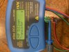
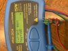
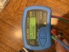
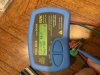
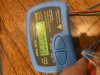
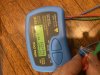
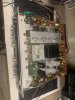
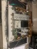
image.jpg image.jpg Guys. Thanks for all the suggestions. I really did take a wrong turn. DC balance was WAY OUT OF SPEC. On the left side, initially would not respond when I move the appropriate adjustment pot. I ended up adjusting R1226, and that allowed the DC balance pot to begin responding. After that, I was able to adjust the DC balance and then power amp bias on both channels. Bingo! Thanks for suggestion Dan!!
I have to say I am freaking thrilled. I played it at a pretty loud volume for about an hour, with no issues. I plan to get it all buttoned back up, and call it good.
 
Last edited:
Sorry for double post.
 

Attachments

  • 1496DB82-CED4-4259-9CB7-00F74B56E333.jpeg
    1496DB82-CED4-4259-9CB7-00F74B56E333.jpeg
    118.7 KB · Views: 14
  • 1033E8F4-9E42-48A1-8C9A-C636C0CAADD6.jpeg
    1033E8F4-9E42-48A1-8C9A-C636C0CAADD6.jpeg
    98.9 KB · Views: 15
Hello Jamie

After that, I was able to adjust the DC balance and then power amp bias on both channels. Bingo! Thanks for suggestion Dan !!

I did suggest it to you also but you didnt answered me
 
Hello Jamie

After that, I was able to adjust the DC balance and then power amp bias on both channels. Bingo! Thanks for suggestion Dan !!

I did suggest it to you also but you didnt answered me
Yes!!! Thanks so much. Your suggestions really helped me work through the problem. I got so focused on the components which really took me down a frustrating path.
 
Back
Top Bottom