• The move to the new server is done. There are some software and database maintenance updates in process. This has us passing the hat around to help out. We appreciate any donations. Seriously, even a dollar helps. The payment page may be found here - https://www.audiokarma.org/support.html

Model Nine GX / KR9000 Restoration and Recap

w1jim

I can fix it but good...
Subscriber
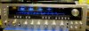
I picked up a nice Kenwood Model Nine GX (the PX or "Audio Club" version of the KR9000) at our recent New England GTG and have begun the fix up.

I will be recapping the amplifier, power supply, tuner, phono, tone and preamp sections. I will not be touching the dolby circuitry since it is obsolete.

The dial and meter lamps will be replaced with LEDs but I'll probably leave the function and speaker lamps alone.
 
Last edited:
Register to hide this ad
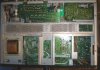
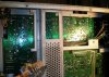
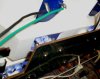
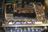
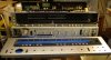
Some disassembly pictures - the front and underside.


attachment.php


attachment.php
 

Attachments

  • Kenwood9GX-front1.jpg
    Kenwood9GX-front1.jpg
    66.6 KB · Views: 222
  • Kenwood9GX-bottom1.jpg
    Kenwood9GX-bottom1.jpg
    100 KB · Views: 225
Last edited:
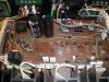
First step - the recapping of the power amp and power supply PCB.
I have not replaced the 2 main power supply caps but have replaced all of the others. 2 1uf caps in the audio path have been replaced with poly film caps.

Parts:
2 - 10,000uf / 70v
1 - 2,200uf / 10v
1 - 220uf / 25v
1 - 220uf / 16v
2 - 47uf / 63v
1 - 47uf / 16v (low loss)
2 - 100uf / 25v
3 - 100uf / 16v
6 - 100uf / 10v
2 - 1uf / 63v (replaced with poly film)
1 - 1uf / 50v
2 - 22uf / 35v (low loss)


attachment.php
 

Attachments

  • Kenwood9GX-Amp-Reg1.jpg
    Kenwood9GX-Amp-Reg1.jpg
    106.8 KB · Views: 225
Last edited:
Next installment is probably a week or so away.
Visiting my daughter in Denver for the week.

Plus I've been trying to determine the best way to pull the tone control PCB without major disassembly - and without having to loosen the dial string.
 
JIM!
OH man ! gonna leave us hangin '''

Enjoy the time "it's family" and be safe.

John M
 
A couple of easy boards while I neglect my other duties.

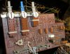
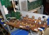
Here's the PCB that controls the Loudness, Mono and dolby calibration.

2 caps total:
1 - 100uf / 25v
1 - 1uf / 50v - replaced with a poly film cap


attachment.php
 

Attachments

  • 9gx-pcb2.jpg
    9gx-pcb2.jpg
    126.4 KB · Views: 176
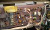
This one is twice as complex - 4 caps.
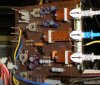
It is the PCB that controls the FM muting, meter scale and meter source.

I also had to unwrap the yellow wire that goes to the post in the upper left corner of the PCB (as seen in the picture) ti get it out and accessible.

2 - 47uf / 10v
2 - 22uf / 35v (low loss)


attachment.php
 

Attachments

  • 9gx-pcb1.jpg
    9gx-pcb1.jpg
    107.4 KB · Views: 171
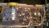
Here's the tone / balance / volume PCB.
It was a bit of a PITA to remove. After loosening all of the screws in it's vicinity (and then some) I found I had to bend one of the metal tags it was screwed to so as to wiggle it out of position.

Parts:
6 - 100uf / 10v
2 - 100uf / 25v
2 - 220uf / 6.3v
2 - 1uf / 50v (low loss) replaced with a poly film
6 - 22uf / 35v (low loss)
6 - 10uf / 25v (low loss)


attachment.php
 

Attachments

  • kw-9gxtone.jpg
    kw-9gxtone.jpg
    91.5 KB · Views: 159
Hey Joe I thought it was the 9600 you had a thing for ??? and the KA --- LOL !!!
Just kidding ...

John M
 
The 9600 and the seperates are more of a curiosity, the 9's and 11's just oooz beauty. They just have a look. Kinda like this woma....nevermind.
 
Now - now, there are plenty of beautiful Kenwoods to go around.
I have a very nice KR-9600 (with the metal case, wood would be nice) and a KR-11000G. Tough life!

One goal of my receiver collection is to have representation of TOTL and near TOTL of the 5 major Japanese manufacturers of the day - Pioneer, Sansui, Yamaha, Marantz and Kenwood.

Now back to the to the Nine GX in progress.

I recapped the Tuner / Phono Preamp / Mike Amp board tonight.

Access to the underside was a bit of a challenge. I did it in place because I didn't want to have to deal with the dial cord (though doing it this way you have to be careful not to touch the iron onto the cord - been there).
I did have to move the dolby PCB out of the way to gain access though.

Cap list:

1 - 220uf / 25v
2 - 100uf / 25v
1 - 100uf / 10v
2 - 47uf / 16v
2 - 47uf / 10v
2 - 33uf / 16v
11 - 10uf / 16v
5 - 1uf / 50v (replaced with poly film)
2 - 3.3 / 10v tantalum (replaced with electrolytics)
2 - 4.7uf / 25v low loss
2 - 1uf / 50v low loss (replaced with poly film)
3 - 0.47uf / 50v low loss (replaced with poly film)
1 - 0.22 / 50v low loss (replaced with poly film)


attachment.php
 

Attachments

  • 9gx-t2.jpg
    9gx-t2.jpg
    101 KB · Views: 138
  • 9gx-t1b.jpg
    9gx-t1b.jpg
    109.6 KB · Views: 41
  • 9gx-t1a.jpg
    9gx-t1a.jpg
    97.4 KB · Views: 42
Yup!! There are plenty to go around! Just picked up an 11g today, the cover is very cosmetically challenged, the face is perfect and it has some kind of weird issue that I have to evaluate. But, I got one!!

Still following Jim, the Kenwood seams to be put together well, looks like it makes sense from my seat here.
 
LEDs

Installed the LEDs for the face / tuning dial.
I'm only illuminating the tuning scale and not the various function indicators (as I did on my KR-11000G).

I wired 2 white / wide-angle LEDs in series in place of each bulb and then put a single 120 ohm / 2 watt resistor in series to limit the current draw. The resistor is inline with the power feed to all of the LEDs.

This mod really makes the face "pop"!


attachment.php


attachment.php
 

Attachments

  • 9gx-leds_a.jpg
    9gx-leds_a.jpg
    60.6 KB · Views: 105
  • 9gx-facea.jpg
    9gx-facea.jpg
    44.8 KB · Views: 108
Last edited:
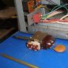
Power switch

I thought I was being a smart-guy when I repaired the lever on the original toggle switch. Problem is that I found the contacts where fused in the "on" position. I tried to open it up and repair it but the guts fell apart on me.

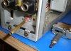
Onto plan B - I took a 3PDT mini toggle switch and a piece of 5/32" brass tubing to extend the lever. Normally I would use a switch with a nut mount but I had this clip in version here so I used that with a little JB Weld to keep it steady.
I put some JB Weld inside the tubing and then crimped it tight.

I found that the original switch had 2 switches in one.
The main contacts and then the small slide switch on top. The small slide switch was "on" when the main power contacts were "off" - probably has something to do with the protection relay.

The original switches power contacts were rated at 5 amps / 125VAC as are the contacts on the replacement switch. I took the liberty of paralleling the contacts on the replacement to double the capacity.
The original .01uf / 250v cap that paralleled the contacts had limited lead length and was bulky so I replaced it with a smaller version I had.

The original toggle switch knob was missing so I used a similar one I had in the parts drawers. A little heatshrink tubing and a touch of silicon sealant to keep the knob in place finished it up.


attachment.php


attachment.php
 

Attachments

  • 9gx-Switch_a.jpg
    9gx-Switch_a.jpg
    94 KB · Views: 240
  • 9gx-Switch_front.jpg
    9gx-Switch_front.jpg
    77.2 KB · Views: 241
Last edited:
Getting ready to wrap it up - tweak the amp adjustments and let it run for a while and we'll be ready to put it into service.


attachment.php
 

Attachments

  • 9gx-topa.jpg
    9gx-topa.jpg
    89.5 KB · Views: 95
Back
Top Bottom