


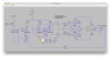
Recently, I've been learning how to model transformers in LTspice, and today I decided to make a SUBCKT for the Heath 54-89 (the power transformer for the AA-100). It seems to work fine. Attached, in case anyone is interested.
The LTspice tutorial is pretty clear on how to do this, and so I just used the rated primary voltage as the inductance value for the primary winding, and then calculating the inductance for each secondary winding as thus:
For a center-tapped winding secondary winding, I connect 2 separate inductors in series with opposite phasing.
So, for the case of the 54-89, it's a 117Vac primary and a 740VCT secondary (370-0-370). So, the primary inductor is assigned:
...and then you connect them all together with a mutual-inductance statement:
The tutorial seemed to indicate that whatever you used for the primary inductance was arbitrary - that it was a starting point for the calculation and nothing more.
Add additional inductors for the remaining secondary windings. Add the DC resistance of each winding as a parameter of that inductor for more accurate results.
Now, what I'd like to do is learn how to model output transformers... but I have no idea how to get the primary inductor(s) defined correctly for the desired primary impedance (once you know the primary, the secondary presumably follows the same formula as for a power transformer). I suspect I actually need to care a bit more about the actual primary inductance instead of using some arbitrary value... but that's just a hunch. I'm just an interpreter (software engineer), and not very good at telling stories (actual electrical engineering).
Any actual-EEs out there who can help me out?
The LTspice tutorial is pretty clear on how to do this, and so I just used the rated primary voltage as the inductance value for the primary winding, and then calculating the inductance for each secondary winding as thus:
Lsec = ((Vsec/Vpri)^2) * Lpri
For a center-tapped winding secondary winding, I connect 2 separate inductors in series with opposite phasing.
So, for the case of the 54-89, it's a 117Vac primary and a 740VCT secondary (370-0-370). So, the primary inductor is assigned:
L1 = 117H
L2 = ((370/117)^2) * 117 = 1170H
L3 = ((370/117)^2) * 117 = 1170H
L2 = ((370/117)^2) * 117 = 1170H
L3 = ((370/117)^2) * 117 = 1170H
...and then you connect them all together with a mutual-inductance statement:
K1 L1 L2 L3 1
The tutorial seemed to indicate that whatever you used for the primary inductance was arbitrary - that it was a starting point for the calculation and nothing more.
Add additional inductors for the remaining secondary windings. Add the DC resistance of each winding as a parameter of that inductor for more accurate results.
Now, what I'd like to do is learn how to model output transformers... but I have no idea how to get the primary inductor(s) defined correctly for the desired primary impedance (once you know the primary, the secondary presumably follows the same formula as for a power transformer). I suspect I actually need to care a bit more about the actual primary inductance instead of using some arbitrary value... but that's just a hunch. I'm just an interpreter (software engineer), and not very good at telling stories (actual electrical engineering).
Any actual-EEs out there who can help me out?


 )
)