• The move to the new server is done. There are some software and database maintenance updates in process. This has us passing the hat around to help out. We appreciate any donations. Seriously, even a dollar helps. The payment page may be found here - https://www.audiokarma.org/support.html

Mono 500 and K-100 Comparison

daylite

Active Member
<------Update: I found a knob for this guy!
TA 500 vs K-100 schematic comparison............Post #1
Under-chassis photographic comparison...........Post #16

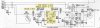
The Model 500 Mono is >95% the same at the K-100 chassis used in some Fisher consoles. The Sams Model 500 service manual is 100x better than the available K-100 service manual. The schematic is laid out much better and available online versions are better quality files – much easier to decipher any small print. Here's the K-100 schematic:

k3poSlG.png


Unlike the K-100 schematic, the 500 schematic includes values for all components and, for coils and transformers, the manual has manufacturer part numbers for replacements. The 500 manual also included photographs that show almost all component placements and lead dress.

I have annotated the Model 500 schematic inserted below to show component item numbers and values for both the 500 and the K-100 on the same sheet. The Model 500 item numbers are all inside circles. Close nearby I’ve added the K-100 numbers and (in cases where values change) the K-100 values. (Fisher did some edits to the 500 schematic with dotted lines and X’s below the 3rd FM IF amp. Not 100% sure I interpreted these right.)

You may count more carefully than I did – but outside the detector and tuning meter areas I find only 6 components with values changed when comparing the 500 and K-100. That’s out of about 200 RCLs. There may be some changes in coils I was unable to document - I do see some part number changes for those. Of course the detector and the meter areas changed (see highlights).

Those of you who love these beautiful old mono receivers might find this useful or at least find it interesting to see the changes. I expect there are mistakes to be found. If I get replies with corrections or suggestions I’ll post a revised version.


GKjANJv.jpg
 
Last edited:
Register to hide this ad
I find outside the detector and tuning meter one of the very few places there is a difference between the K-100 schematic and the 500 Mono schematic is in the phono section. Here's the region:
K-100 Rumble Filter ?.jpg
On the 500 Mono C52/R47 (10000pF/2.2M) make up a high pass filter with 7 Hz cutoff. I guess this was meant as a rumble filter. On the K-100 the corresponding components (C39/R44 4700pF/1M) give a cutoff of 34 Hz. That seems high to me - maybe worth a change to get a little more bass? The resistor would have to go to 5 meg if the 4700 pF is kept. Maybe better to keep the 2.2M at R44 and go to 22 nF for C39? The values above for the filters are on the parts list and confirmed to be there under the hood, at least on my K-100. [The apparent difference in R45/R50 on the cathode I think is a typo. The K-100 parts list gives 220 ohms, but it's actually a 2200 ohm part, matching the 500 Mono part, when checked in the circuit. Note the RIAA/NAB/etc network is not a PEC on these models and is the same for both.]
 
Last edited:
The Sams schematic shows EL34 output tubes; of course they were EL37. With 5881s, an additional 50 Ohm common cathode resistor was added; 6L6GCs might take the lower bias voltage OK, but the power transformer won't be happy about the additional current.
 
Thanks - that's helpful. The K-100 chassis had new issue 6L6GCs when it came to me. So far that's the only type of tube I have tried. I installed an individually variable voltage bias supply because as the unit was received (stock fixed* bias) they were running VERY hot.. I'm running them now at 60% (46 mA at 390 V).
EDIT: *I learned below it's 'back bias'. Thanks gadget.
 
Last edited:
On the K-100 the corresponding components (C39/R44 4700pF/2.2M) give a cutoff of 34 Hz. That seems high to me - maybe worth a change to get a little more bass?

Were these used in consoles? That might explain the filter frequency. Turntable parked right above the speaker is a prime environment for feedback.

gut feeling is that measured performance won't be as different as you suspect. Since the EQ is done via feedback, that would do a lot to compensate for any roll-off within the feedback loop.
 
Yes - I think this was used in the Normandy. Seems to me Larry mentioned he had a Normandy. (EDIT: I was wrong on both of these!)

I had a feeling the benefit might not be worth the effort, but thanks for providing the technical knowledge about feedback to reinforce that idea. I haven't made any change.
 
Last edited:
Not me. '51 Coronet with an R-3 Chassis. P-P-P 6V6. And yeah Gadget, the K-100 was put in both the '57 and '58 Custom Electra II's.

It's highly conceivable that the K-100 was a kissing cousin or a half sister to the original 500. I've just glossed over the thread, but the similarities in circuits are definately intriguing.
 
honestly it makes more sense financially to recycle an existing design with some tweaks than to create a totally new one if you already have something that mostly does what you want.
 
right, gadget. nothing at all wrong with that plan. I imagine someone at Fisher saying 'hey - we have some great circuit design in our consoles. let's pull one out and make a standalone receiver.' With the K-100 as the starting point, it was a very short path to the 500 Mono. They are really the same power supply, fm tuner, amp, and phono section. Fisher did make a wise choice to drop the out-of-date / out-of-fashion magic eye, and they designed a nice cabinet.
 
Sorry Larry. My brain garbled a memory of your comments from this thread –
https://audiokarma.org/forums/index...-custom-electra-i-in-normandy-cabinet.471818/ Now I see you didn’t comment about having a Normandy but did mention the Coronet.

The Normandy and the K-100 and Custom Electra were linked in my mind by reading a Radiomuseum entry:
https://www.radiomuseum.org/r/fisher_custom_electra_ii_k_100.html
Also the attached report of a console restoration claims the K-100 was in at least some Normandy consoles. But folks (especially me!) can be wrong.
 

Attachments

Last edited:
....I installed an individually variable voltage bias supply because as the unit was received (stock fixed bias) they were running VERY hot.. I'm running them now at 60% (46 mA at 390 V).

Curious: How did you accomplish this?
 
huh. Its back bias, not actually fixed bias. Had to take a closer look at that. For a second I thought they forgot to draw in the diode, but there is no diode. Bias develops across R81 in parallel with the 3 tube heaters. Its basically cathode bias, but shuffled around slightly. Only real difference is you get current flow from all tubes rather than just the output tubes, so in theory it should shift slightly less from idle to full power.

Problem with this setup you can't easily add more negative voltage in order to drop the current down unless you change the value of the shunt resistor. That puts more voltage across the tube heaters though which isn't good for their life.

I suppose you could make a proper fixed bias supply by using a diode and one of the 6x4 plate leads. Couple resistors and caps would easily give a source that could be adjusted as needed using trim pots
 
huh. Its back bias, not actually fixed bias. Had to take a closer look at that. For a second I thought they forgot to draw in the diode, but there is no diode. Bias develops across R81 in parallel with the 3 tube heaters. Its basically cathode bias, but shuffled around slightly. Only real difference is you get current flow from all tubes rather than just the output tubes, so in theory it should shift slightly less from idle to full power.
gadget - thanks for explaining. I haven't come across the term 'back bias' in my slow journey of self-learning. I'll start looking it up and also hope to find out what qualifies as 'fixed bias'.
[EDIT: I put a K-100 schematic into the first post in this thread and highlighted R81.]
 
Last edited:
Its an old method, usually seen more on pre-war equipment. Sometimes they would use the field coil of the speaker instead of a resistor. Honestly the only reason I'm at all familiar with it is I got into tube hifi gear from antique radios.

Fixed bias isn't dependent on circuit load, so usually its produced with a solid state diode or a battery way back in the ancient times. I have a radio from 1926 that uses a 4.5 volt "C" battery for this job. It "fixes" the grid at some negative voltage relative to the cathode rather than having to rely on current flow to develop the voltage.
 
pBUxiKN.jpg

I liked the ‘Game of Seven Differences’ the newspapers ran when I was a kid. The goal was to look at two drawings and find seven differences between them. I’m not finding much here. Given the above views of two receivers we might think we were looking at two examples of the same product. Different serial number, built on different days, but the same model.

On the left is a picture of a 500 Mono (TA 500) chassis and on the right hand is a picture of the K-100 chassis.

Before seeing these photos I didn’t notice that the change in the value of the coupling cap between sections of the phono stage 12AX7 (see post #2) also involved a change in the type of cap. Fisher used a Marbelite 4.7 nF paper cap in the K-100 (C39) but a 10 nF disc cap in the 500 Mono. (In the pics the base of that 12AX7 is just below the selector switch.) I checked my K-100 and the part number on the output transformer is the same as that visible in the 500 Mono photo. The power transformer part numbers also match. -d
 
Last edited:
If you looked at this earlier thread or above, you’ll know I have a Fisher K-100, a mono FM-AM receiver that was used in consoles in 1958. Here’s an example. Sometimes a console radio chassis comes up for sale without the rest of the console. I guess people like the furniture part and replace the old insides with ‘up-to-date’ stuff. Or they really hate the furniture, or it got damaged, or they have no room but don’t feel good about throwing away the insides, maybe planning to someday do something with the inside stuff or sell it. The chassis becomes ‘disembodied’.

I saved a disembodied K-100 chassis that came up for sale. Here’s a little about it in a newer post. During the project I built an enclosure for the chassis. The K-100 looked like this before the project. It looked like this after the project. You’ll notice it was missing a knob (the back part of one of the larger diameter two-tier knobs). The ‘after’ shot shows a replacement I made that ‘sort of’ looked OK - from a distance - but bothered me. That’s a front shot of it with the fake knob in my profile picture on the left.

Today I’m celebrating finding a perfect original replacement knob! It turned up on the auction site. Not much more to say except sometimes what we want will turn up, I’m happy it happened this time, and here’s the celebratory picture showing the knob in place:

KVt5dYO.png

-d
 

Attachments

  • Custom Electra II.jpeg
    Custom Electra II.jpeg
    121.8 KB · Views: 33
  • K-100 as received.JPEG
    K-100 as received.JPEG
    171.8 KB · Views: 35
  • FrontFace K-100 Old Knob.jpg
    FrontFace K-100 Old Knob.jpg
    105.7 KB · Views: 38
Last edited:
I'm not into Mono sets usually, but I gotta say that what you did with that K100 is just beautiful. Good work on the wood and metal face!

BTW, how did you create that metal panel and how did you get the brass coloration? Is that the color of the metal or a lacquer to get that hue?
 
Hi, Tim. Thanks - it’s anodized aluminum, satin gold, 0.025”. It’s sold for many purposes, but one big use is for engraving to make plaques and trophies. An online search for “aluminum sheets for engraving” will turn up a lot of suppliers including the one I used. The project needed a piece 12-7/8” long, or I might have gotten the 4”x12” piece one supplier had for $8.

Lucky for me they couldn’t make over 12” pieces. I ordered a 12”x24” piece elsewhere for less than twice what they wanted for the 4”x12”. So I’m all set for my next project rescuing a disembodied Fisher! -d
 
Last edited:
If you looked at this earlier thread or above, you’ll know I have a Fisher K-100, a mono FM-AM receiver that was used in consoles in 1958. Here’s an example. Sometimes a console radio chassis comes up for sale without the rest of the console. I guess people like the furniture part and replace the old insides with ‘up-to-date’ stuff. Or they really hate the furniture, or it got damaged, or they have no room but don’t feel good about throwing away the insides, maybe planning to someday do something with the inside stuff or sell it. The chassis becomes ‘disembodied’.

I saved a disembodied K-100 chassis that came up for sale. Here’s a little about it in a newer post. During the project I built an enclosure for the chassis. The K-100 looked like this before the project. It looked like this after the project. You’ll notice it was missing a knob (the back part of one of the larger diameter two-tier knobs). The ‘after’ shot shows a replacement I made that ‘sort of’ looked OK - from a distance - but bothered me. That’s a front shot of it with the fake knob in my profile picture on the left.

Today I’m celebrating finding a perfect original replacement knob! It turned up on the auction site. Not much more to say except sometimes what we want will turn up, I’m happy it happened this time, and here’s the celebratory picture showing the knob in place:

KVt5dYO.png

-d
Good work and great pics.
 
Back
Top Bottom