• The move to the new server is done. There are some software and database maintenance updates in process. This has us passing the hat around to help out. We appreciate any donations. Seriously, even a dollar helps. The payment page may be found here - https://www.audiokarma.org/support.html

MPSA65 Darlington hFE

ocdecio

The proof of the restoring is in the listening.
Subscriber
I followed lots of threads about the 240/250 and one thing I remember reading was Q503 can be a troublemaker, and it is a darlington MPSA65. I am having issues with the left channel slowly getting pops and cracks, then all of a sudden a "whoosh" and bam, the channel is out with rails DC in the output (protection prevents it from going to the speakers thank goodness).

I pull Q503 and measure an hFE of 35K. As per the datasheet it should be above 50k:

upload_2021-3-22_21-4-7.png

I got two batches of MPSA65. The ones from Little Diode measure from 7k to 11k to my disappointment (fakes?). Fortunately the batch from bdent has a couple of 90k so I put one in. I am not yet 100% this is the problem but the amp is working so far.

My question to anyone that came across these MPSA65 - what was the hFE you measured on them? Is 35K OK? or should it indeed be around 90K?
 
Register to hide this ad
Well, it's above 50K with a collector current of 10mA. Who knows what the tester is using for current? If it's something dedicated (Cricket series?) you could perhaps insert a current meter, but if it's a tester like an Atlas DCA, they run a litany of tests so it would be pretty difficult if not impossible to make a measurement.
 
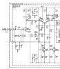
@rBuckner true. I just found it odd that I would get two batches so far apart (well measured with the same tester). I wonder if this is one of these cases where higher hFE is better or not, and what the effects of a lower hFE or a higher hFE would be. The SM states Q503 is a "high gain inverter" driven by the diff pair. The inverter feeds the pre-driver pair.
 
Only guessing here - I am no amp expert. I would guess that the usage of a darlington transistor for Q503 would be to do minimal loading on the diff pair, specifically Q502. So if the gain were too low it may "drag" on Q502 with the effect perhaps being lower signal levels or maybe distortion? So I would think that higher is better. AGAIN - only postulating here!!
 
@rBuckner You must be onto something here. At one point I had the drivers (Q510 and Q511) very far apart in hFE and this problem with a channel going to rails was more severe and one of the consequences when it happened is that one of the differentials apparently got damaged. I say apparently because the one thing I was able to measure is that its hFE dropped from 420 or so to 300. As soon as I put a new pair it would go back working for a while and again fail a couple of days later.
So I went to great lenghts to get a driver pair that was very close. This allowed me to run the amp for more than a month until this week where the same thing happened but this time the diffs were not affected. I took them out, measured, they still matched. I put them back and everything is back to normal.

So what you are saying may indicate that Q503 was also part of the problem/imbalance. I will run it some more and see.

Thank you for your insight!
 
I am not convinced that HFE alone is causing this problem. Sounds like a noisy or intermittent transistor to me. Get some freeze spray and squirt a small amount on each TO-92 transistor, one at a time, watching the output (before the relay) with a scope. Replace any transistor that causes a large offset.
 
I am not convinced that HFE alone is causing this problem. Sounds like a noisy or intermittent transistor to me. Get some freeze spray and squirt a small amount on each TO-92 transistor, one at a time, watching the output (before the relay) with a scope. Replace any transistor that causes a large offset.
Got the spray, got the scope. Just making sure - I should watch the DC offset before the relay correct? Or should I inject some signal to the input - and if so, should I connect a dummy load?

Thank you!
 
I am not convinced that HFE alone is causing this problem. Sounds like a noisy or intermittent transistor to me. Get some freeze spray and squirt a small amount on each TO-92 transistor, one at a time, watching the output (before the relay) with a scope. Replace any transistor that causes a large offset.
I agree. Something is changing/failing in a larger way... it's not just a gain change.

Got the spray, got the scope. Just making sure - I should watch the DC offset before the relay correct? Or should I inject some signal to the input - and if so, should I connect a dummy load?
Thank you!
I'm going to guess that a dummy load should not be installed. Freeze spray will cause transistor gain to change and may rail the outputs at worse. A load would make the outputs go kablooie.
 
@rBuckner thank you, glad I asked.
Correct, scope before the relay, no input signal, no speakers or load connected. If there is DC on the output a load would draw current and possibly damage the output transistors. With no load there is very little current. With DC on the output, one half of the amplifier is on, the other half is turned off, so there is nowhere for the current to go as long as there is no load.
 
@dr*audio thank you for the guidance. One thing I noticed and was trying to calculate is that Q519 and Q518 (the input emitter follower and its current source) get hotter than others (around 140-150F). I am not going to hit these because as far as I can tell they don't participate in the DC balance circuit (please correct me if I am wrong).
 
Check the voltage on CR501 and CR502. they appear to be 18V Zeners. According to the voltages on the schematic, Q518 should only have 125uA through it. Multiply that by the voltage from Emitter to Collector (13.6V) and you get 1.7mW of dissipation in the transistor. Something is not right. Check the voltages.The same current flows through Q519 and the voltage across it is the same so the dissipation is the same. The parts should not be hot at all!
 
Here's my readings:

CR502 (1N967B): 18.45V
CR501 (1N967B): 18.40V
R549 (5.6K): 17.8V (~ 3.mA)
R548 (270): 0.84V (~ 3 mA)

Dissipation over Q518 ~ 52mW (considering the voltage at its base 17V)

Temp measured with cheapo laser termometer on Q518 = 155F

Another observation - C501 (silver mica 150pf) gets 120F. Not sure if this can be an issue.


upload_2021-3-24_9-12-41.png
 
What are the voltages on Q519?

EC = 17.57V
BC = 16.60V
BE = 0.531V


BTW this may be relevant - this used to be a SPS1928 (unobtainium) that was replaced with a BC550C

Voltages across Q518 (BC557B-A30) used to be MPS6519:

EC = 18.25V
BC = 17.65V
BE = 0.60V
 
Last edited:
Voltages referenced to ground, please? For both transistors.


EC = 17.57V
BC = 16.60V
BE = 0.531V


BTW this may be relevant - this used to be a SPS1928 (unobtainium) that was replaced with a BC550C

Voltages across Q518 (BC557B-A30) used to be MPS6519:

EC = 18.25V
BC = 17.65V
BE = 0.60V
 
Last edited:
@dr*audio sure:

Q518
B: 17.01V
E: 17.55V
C: -0.58V

Q519
B:-0.04V
E: -0.572V
C: 17.03V

Hope I didn't make a mistake.
 
Those measurements look good and the power dissipation through the transistors is too low to be heating them up. Perhaps there is some other component nearby that is getting warm. Likewise, C501 has 0V across it, there is nothing to heat it up. I bet it's radiated heat from Q508.
 
Last edited:
Back
Top Bottom