• The move to the new server is done. There are some software and database maintenance updates in process. This has us passing the hat around to help out. We appreciate any donations. Seriously, even a dollar helps. The payment page may be found here - https://www.audiokarma.org/support.html

MR77 Loss of MPX?

pgena

Member
My Mr77 sounds fine, but at around 10 minutes after power-up, the right channel gives way completely to white noise. Though the station is strong (6+), a quick turn of the Stereo Filter switch to 1 returns the sound on the right and the sound is clear for the duration. If I switch the filter back out, the right channel is clear for about a minute until it's lost again. The Filter makes a popping sound with each turn. When I change the mode to Mono, the right channel is still bad.

Having heard the tantalum horror stories, I switched them out on the MPX and output amplifier boards, even the "ghost" C8 tantalum (which, as noted in earlier threads, doesn't exist on the schematic or on the image of the printed circuit board in the MR77 service manual - for the batch in which my serial number lies).

When I powered up, the C8 replacement literally blew up! I'm guessing that the polarity might have been incorrect - I had the negative going to ground. That may have been the cause, but it was a crap shoot without this "ghost" appearing on the schematic, as I couldn't decipher the polarity on the old blue tantalum. I cleaned up the mess and left C8 out of the circuit (again, in a previous thread some questioned its purpose anyway).

I powered up the unit again, and I must say that there was a noticeable improvement in sound, and I thought that this work may have eliminated the rt. channel noise issue. Alas, to my chagrin the noise returned after the ten-minute warmup, behaving the sam way. I would appreciate any thoughts or direction. Thanks!
 
Register to hide this ad
The tantalum cap, the phantom as you describe it, is there to filter out any high frequency noise on the supply voltage.

Does the stereo light go out when you lose the channel? If the channel just drops out but the MPX light stays on I would suspect a failing device in the output section.
 
Thanks c_dk! I'll look into the output section, but I don't know why the rt. channel comes back for the duration when I switch the Stereo Filter in. Do you know if the positive side of the C8 cap is supposed to go to ground? I'm reluctant to reconnect it until I know. The parts list shows the C8 cap, but it's not to be found anywhere in the schematic or circuit image.
 
Hello pgena
I don't see any c8 capacitor on MPX pcb
All capacitors on MPX pcb are starting by C300
I found a C8 in schematic but this is not on MPX board
 
It is hard enough to sort these tuner out while right in front of you let alone 200 miles away.

I believe I have 4-5 schematics for these two tuners and I do know one of them has the "phantom" tantalum cap displayed.

I beleve it is actually C308, I think you might have installed C325 in backwards, the + on that one goes to ground since it is in the -12 volt supply line. The "phantom" is in the + 24 volt line so it would have the - to ground.

As for the channel dropping out, bench sorting out time could be hours, there are lots of opportune possibilities.
 
I dug thru my schematics and #039233 for the mr78 serial #AD5175 thru 9999 and then restarting with CG1001 pictures the "phantom cap"

It is C308 and is located 3/4s of a inch (13mm) directly to the right of the orange 24 volt supply wire (pin3).

Since all the kids are out of the house now I do not get yelled at because the scanner/ printer is down and off line so not able to scan at this time.

Why only the last schematic has this redrawn layout I do not know.......must have something to do with the secret handshake.
 
It is C308 and is located 3/4s of a inch (13mm) directly to the right of the orange 24 volt supply wire (pin3).

Why only the last schematic has this redrawn layout I do not know.......must have something to do with the secret handshake.
Good find, I think it has to do with QA and company document control standards. If Mc did that with Defense projects, they'd be raked over the coals in design reviews.

Actually the Gov would give them more money to implement those standards, as they typically do. :smoke:
 
Hello pgena
I don't see any c8 capacitor on MPX pcb
All capacitors on MPX pcb are starting by C300
I found a C8 in schematic but this is not on MPX board

C308 is easy to find. It was replaced here with a 10uF Nich FG (Fine Gold).

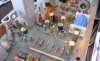
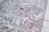
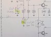
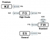
MPX_PCB_recapped_734_C308.jpg C308_PCB.jpg C308_schematic_emh.jpg Nich_caps.png

Hope that's correct. Included is a Nich electrolytic diagram.

The MR77 has been running here most every days 4- 6 hrs for the past 1-1/2 to 2 years.

If you think of it, could you measure and post the AC line draw in Watts for you MR77?


-Greg
 
Last edited:
Hello Greg
C308 is easy to find , yes , but not C8
I don't have any MR77 right now , but as soon I get one , I will let you know without delay
 
I believe I have 4-5 schematics for these two tuners and I do know one of them has the "phantom" tantalum cap displayed. I believe it is actually C308. The "phantom" is in the + 24 volt line so it would have the - to ground.
Now it's coming back to me years after the update in Jan 2014.

Had to look carefully at the schematic and PCB to find the cap location and drawn it in. This is from MR77 SI booklet 038-609.

C308_phantom_cap.jpg

So there's the PHANTOM cap! :smoke:


-Greg
 
Last edited:
Thanks everyone! Please forgive my inadvertent shorthand in writing C8 (senior moment) - it is indeed C308. There was no problem seeing it on my actual board. Thanks for the advice c_dk, but I double-checked C325 and it is in fact wired correctly. In fact I checked all polarities of the new caps. I though that I had wired the new Nichicon on C308 correctly (minus to ground), but couldn't tell after it blew sky high! I guess I could try again at a distance.

As for the right channel noise kicking in after 10 minutes, I should mention that it cuts out all the music signal on that side. When I set the Stereo filter switch to 1 (or 2) all is well. Something appears to fail after warmup, and the filter circuit somehow compensates? I notice that when the filter switch is out, its circuitry is bypassed anyway! Trouble-shooting the output section with my limited experience—armed with just a VTVOM, capacitance meter, and variac—may take some time. A call to McIntoshlabs or Audio Classics (if not a shipment) after the pestilence subsides may be in order.
 
Back
Top Bottom