FireGuruMN
Active Member
I recently picked up a MX-1 for "parts/repair". . The speaker switches were pushed in from the pictures and the description said it did not power up. I've always been an optimist. It showed up nicely packaged.
I pulled the cover off. It looked very clean and there was no obvious damage. I pulled the front face off. The speaker switches were pushed in and the metal bracket tabs were was bent. No bid deal to put the switches back and bend the metal back in place.
The power switch assembly circuit board was cracked in half. I super glued it back into one piece, cleaned some of the covering off the traces and put in a few solder bridges. It metered ok.

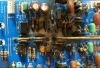
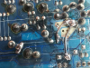
I plugged the amp in and it powered up on a DBT with no surprises. But the protection relays did not pull in. I checked and I had good 70vdc from the power supply to the amp boards. I didn't check any of the other voltages on the power supply. I checked the bias on the emitter resistors per the manual. Some were around 3.6mv. But several were at 0.0mv on the left and on the right. So I looked at things a little closer. I noticed one of the emitter resistors pins had been pushed through the PCB and pulled the trace off. Wow, what sort of fall could cause that? So I pulled the heat sink out to take a better look at the back side. That is when I noticed this:
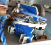
That took some effort to crush the board that much. But if you look closely the fuse is still in the socket on both sides to the amp still powered up! It's like it wants to live again. Here is sort of what I expected to find on the left side:
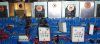
Here is the back side of the PCB:
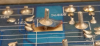
That actually looks repairable. Just some jumpers or solder bridge over to the little pins by the "c217" on the PCB. Just enough so it can handle the current. Obviously I have a pile of transistors that will need replacing. I saw another thread that had recommended replacements. I'll have to see if they are still good part numbers. But I pulled the right PCB and I could not see anything wrong with it. I did not pull the transistors but there were no shorts or opens that I could identify. Resistances all looked similar. Then I saw some blackened ribbon cables under the main capacitor board. So I pulled that board out:
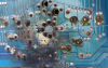
BLEWEY! Was this thing powered up when it fell? The manual does not have a PCB diagram for this board. I think I am going to need one. Anyone got a diagram? Or does anyone have a replacement board? There are not a lot of components on this board in this area. Just a bunch of grounds, jumpers and plugs. I'm thinking I could probably find enough copper traces to rebuild this. But also see that at least one big pin is pushed through in the upper right. It might look better once I clean off the blackness.
Yamaha went to a lot of effort to get the grounding right. I love the star ground component. Am I going to mess it up putting in jumpers and such? I am thinking that I had 0.0 bias on the right amp board because it was not getting any power from this blowout. Does that seem possible?
So what do you think? Can all the kings horses and all the kings men put this back together again? If these are the only problems that exist, I think it is possible but I'd sure like to get a new power supply board.
I don't need another boat anchor. . .
I pulled the cover off. It looked very clean and there was no obvious damage. I pulled the front face off. The speaker switches were pushed in and the metal bracket tabs were was bent. No bid deal to put the switches back and bend the metal back in place.
The power switch assembly circuit board was cracked in half. I super glued it back into one piece, cleaned some of the covering off the traces and put in a few solder bridges. It metered ok.
I plugged the amp in and it powered up on a DBT with no surprises. But the protection relays did not pull in. I checked and I had good 70vdc from the power supply to the amp boards. I didn't check any of the other voltages on the power supply. I checked the bias on the emitter resistors per the manual. Some were around 3.6mv. But several were at 0.0mv on the left and on the right. So I looked at things a little closer. I noticed one of the emitter resistors pins had been pushed through the PCB and pulled the trace off. Wow, what sort of fall could cause that? So I pulled the heat sink out to take a better look at the back side. That is when I noticed this:
That took some effort to crush the board that much. But if you look closely the fuse is still in the socket on both sides to the amp still powered up! It's like it wants to live again. Here is sort of what I expected to find on the left side:
Here is the back side of the PCB:
That actually looks repairable. Just some jumpers or solder bridge over to the little pins by the "c217" on the PCB. Just enough so it can handle the current. Obviously I have a pile of transistors that will need replacing. I saw another thread that had recommended replacements. I'll have to see if they are still good part numbers. But I pulled the right PCB and I could not see anything wrong with it. I did not pull the transistors but there were no shorts or opens that I could identify. Resistances all looked similar. Then I saw some blackened ribbon cables under the main capacitor board. So I pulled that board out:
BLEWEY! Was this thing powered up when it fell? The manual does not have a PCB diagram for this board. I think I am going to need one. Anyone got a diagram? Or does anyone have a replacement board? There are not a lot of components on this board in this area. Just a bunch of grounds, jumpers and plugs. I'm thinking I could probably find enough copper traces to rebuild this. But also see that at least one big pin is pushed through in the upper right. It might look better once I clean off the blackness.
Yamaha went to a lot of effort to get the grounding right. I love the star ground component. Am I going to mess it up putting in jumpers and such? I am thinking that I had 0.0 bias on the right amp board because it was not getting any power from this blowout. Does that seem possible?
So what do you think? Can all the kings horses and all the kings men put this back together again? If these are the only problems that exist, I think it is possible but I'd sure like to get a new power supply board.
I don't need another boat anchor. . .


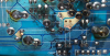
 . Neither option will help me sleep at night. Is there a handy website for finding modern replacements? How will I know that they are up to the original standards (or better)?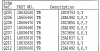

 I'll start with the melted board and if I have parts left over I can move to the other side.