


Carbsandcaps
Super Member
About a year ago I was surfing eBay and came across this diy 300b amplifier board and figured why not find out what these tubes are all about? So I ordered in for $70. It’s just the board, no power supply, no tubes, no output transformers ect. Then I started to collect the parts.
I went over to alibaba and found some amorphous (whatever that meant) 10watt output transformers with 4-8-16 ohm and 2500ohm and 3500ohm primaries for $150 for the set. Back to eBay and found a matched set of psvane 300b’s for another $150. I had a set of Westinghouse 6sn7’s laying around already.
I had a philco power transformer with the rectifier tube out of the top of it that I had been looking for something cool to do with and this seems like a nice fit. The kit called for 320vdc and guess what. This thing puts out 340vdc almost perfect! After some testing I figured out that it was using full wave rectification so should be good to go.
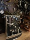
Now the problem. It only put out 6.3v heater voltage. Fine for the 6sn7’s but not so much for the 5v heaters in the 300b’s. I ran a string of resistors (3 or 4 ohms I think) to get it down to 5v along with the 6sn7 heaters but then i figured that would be too much stress on the power supply so there had to be another way. Well everything runs on 5v now so there had to be some decent 5v power supplies out there. Back to eBay and I came across this lambda regulated 5v 3 amp power supply assembly for $30. Ordered! I found a Hammond choke that matched the specs that the kit called for too.
I figured if I’m using dc voltage for the output heaters I might as well use it for the drivers. The pcb rectifies the 5vac input for the 300b heaters and since I wasn’t using that circuit I decided to use it for the driver heaters. After modifying the pcb, diodes and capacitors to rectify the incoming 6.3v instead of the 5v I turned on the transformer. I had about 7vdc. I wanted to get closer to 6.3vdc so after trying some different resistors I ended up with a .5ohm 5 watt resistor to bring it down to 6.4vdc to the 6sn7’s.
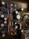
The board was pretty straight forward to assemble. It comes with everything however some of the resistor values in the kit didn’t match what was written on the board so I decided to go with the board and use some of my own resistors. The original plan called for a 68uf capacitors BEFORE the choke. Way too much for the power supply so I dropped it down to 22uf. The enormous 470uf cap after the choke will take care of any ripple. I had to cut traces out and run some new wires across the the board to accommodate the new heater supply circuits. The board also used a rectifier tube which I would be needing so I wired the power transformer output to the original output of the 5u4 socket. The end result is anything but pretty but it works.
Now to find a suitable chassis for it all. I tried an attache case, a number of wooden cases and basically anything I could find. It had to be pretty wide to fit the ot’s next to the pt and those ot’s are big! Then one day I came across a Harmon kardon console with a 224 tube receiver and a Garrard turntable. The console wasn’t salvageable and the receiver was barely salvageable due to mouse urine and god knows what else so I gutted it. While I was loading the carcass into the dumpster I took one more look at the drawer that the turntable sat in and slid in and out. It was perfect! I had my dad who’s retired and dabbles in woodwork to make me a top and bottom for the drawer since it just had a cutout for a turntable. He made the top and bottom, stained them and cut the holes for the board and pt.
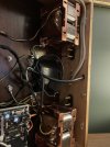
Not the finally assembly. I decided to put the output transformers on the inside of the cabinet because well they’re ugly. The con comes with standoffs and screws. I disassembled the pt to out longer mounting screws in. The wiring was straight forward but I decided to go with a 3 prong plug and since I’m ising a wooden chassis I had to run jumper wires to everything metal. Wired up some speaker terminals and input terminals and chopped up an old rca cable to run form the input jack to the pcb.
Now it’s the scary part, time to fire it up, I plugged in and turned it on. Everything can on but the heaters in the 300b’s. I checks and found no output from the 5v power supply. Started looking around and saw a voltage and limit adjustment. The draw of the heaters was higher than it was set for so after some adjustments I finally got it to turn on. Adjusted to 5.00v and was good to go. I can not believe this thing worked the first time I turned it on and nothing blew up! Not bad for some scrap parts and less than $500.
Then I started playing some music. Good god this is what all the hype was about! It sounds incredible. I hear parts of songs that I’ve never heard before. And absolutely no hum. I know it only puts out 10 or so watts but there’s plenty of volume. If I spend $10k on a matched pair of western electric 300b tubes will it make a difference? Who knows but I’m happy with how it is now. The is my first direct heated triode but it certainly won’t my last, I think I’m hooked!

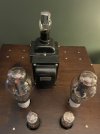

I went over to alibaba and found some amorphous (whatever that meant) 10watt output transformers with 4-8-16 ohm and 2500ohm and 3500ohm primaries for $150 for the set. Back to eBay and found a matched set of psvane 300b’s for another $150. I had a set of Westinghouse 6sn7’s laying around already.
I had a philco power transformer with the rectifier tube out of the top of it that I had been looking for something cool to do with and this seems like a nice fit. The kit called for 320vdc and guess what. This thing puts out 340vdc almost perfect! After some testing I figured out that it was using full wave rectification so should be good to go.
Now the problem. It only put out 6.3v heater voltage. Fine for the 6sn7’s but not so much for the 5v heaters in the 300b’s. I ran a string of resistors (3 or 4 ohms I think) to get it down to 5v along with the 6sn7 heaters but then i figured that would be too much stress on the power supply so there had to be another way. Well everything runs on 5v now so there had to be some decent 5v power supplies out there. Back to eBay and I came across this lambda regulated 5v 3 amp power supply assembly for $30. Ordered! I found a Hammond choke that matched the specs that the kit called for too.
I figured if I’m using dc voltage for the output heaters I might as well use it for the drivers. The pcb rectifies the 5vac input for the 300b heaters and since I wasn’t using that circuit I decided to use it for the driver heaters. After modifying the pcb, diodes and capacitors to rectify the incoming 6.3v instead of the 5v I turned on the transformer. I had about 7vdc. I wanted to get closer to 6.3vdc so after trying some different resistors I ended up with a .5ohm 5 watt resistor to bring it down to 6.4vdc to the 6sn7’s.
The board was pretty straight forward to assemble. It comes with everything however some of the resistor values in the kit didn’t match what was written on the board so I decided to go with the board and use some of my own resistors. The original plan called for a 68uf capacitors BEFORE the choke. Way too much for the power supply so I dropped it down to 22uf. The enormous 470uf cap after the choke will take care of any ripple. I had to cut traces out and run some new wires across the the board to accommodate the new heater supply circuits. The board also used a rectifier tube which I would be needing so I wired the power transformer output to the original output of the 5u4 socket. The end result is anything but pretty but it works.
Now to find a suitable chassis for it all. I tried an attache case, a number of wooden cases and basically anything I could find. It had to be pretty wide to fit the ot’s next to the pt and those ot’s are big! Then one day I came across a Harmon kardon console with a 224 tube receiver and a Garrard turntable. The console wasn’t salvageable and the receiver was barely salvageable due to mouse urine and god knows what else so I gutted it. While I was loading the carcass into the dumpster I took one more look at the drawer that the turntable sat in and slid in and out. It was perfect! I had my dad who’s retired and dabbles in woodwork to make me a top and bottom for the drawer since it just had a cutout for a turntable. He made the top and bottom, stained them and cut the holes for the board and pt.
Not the finally assembly. I decided to put the output transformers on the inside of the cabinet because well they’re ugly. The con comes with standoffs and screws. I disassembled the pt to out longer mounting screws in. The wiring was straight forward but I decided to go with a 3 prong plug and since I’m ising a wooden chassis I had to run jumper wires to everything metal. Wired up some speaker terminals and input terminals and chopped up an old rca cable to run form the input jack to the pcb.
Now it’s the scary part, time to fire it up, I plugged in and turned it on. Everything can on but the heaters in the 300b’s. I checks and found no output from the 5v power supply. Started looking around and saw a voltage and limit adjustment. The draw of the heaters was higher than it was set for so after some adjustments I finally got it to turn on. Adjusted to 5.00v and was good to go. I can not believe this thing worked the first time I turned it on and nothing blew up! Not bad for some scrap parts and less than $500.
Then I started playing some music. Good god this is what all the hype was about! It sounds incredible. I hear parts of songs that I’ve never heard before. And absolutely no hum. I know it only puts out 10 or so watts but there’s plenty of volume. If I spend $10k on a matched pair of western electric 300b tubes will it make a difference? Who knows but I’m happy with how it is now. The is my first direct heated triode but it certainly won’t my last, I think I’m hooked!


