

You are using an out of date browser. It may not display this or other websites correctly.
You should upgrade or use an alternative browser.
You should upgrade or use an alternative browser.
My Boston A400 rebuild
- Thread starter tromba
- Start date

Andy_H
Behind the Wall of Sleep
Still working on getting the upper crossover out. In the meantime....
Here's a photo of the lower crossover. (Remember this is new to me.) Am I right that #3 and #4 are the caps? What are #1 and #2

1 and 2 are inductors (coils), 3 is a resistor, and 4 is a pair of electrolytic capacitors. Only the capacitors should need replaced here. Helpful in determining a what a component is are the values marked on it. Inductors are measured in henries (usually millihenries in crossovers) marked mH, resistors are measured in ohms marked with the Greek letter omega Ω, and capacitors are measured in farads (F) (usually microfarads in crossovers) marked with the Greek letter mu µF or spelled as "uF" or "MFD". The percentage is a tolerance rating - it is manufactured with a tolerance of X% of the stated value. So in #3 you have a 10 ohm resistor with 10% tolerance.
I can never remember how capacitance is added or multiplied or whatever in series or parallel, etc, so I'll leave that to someone more knowledgeable to figure out. I do know that with regard to the voltage ratings, you are fine to go over the original rating, you just need to meet or exceed whatever rating is on the part you are replacing.

tromba
Super Member
Thanks for that reply!! That's a great help.
I just got the upper crossover out, and here's what it looks like
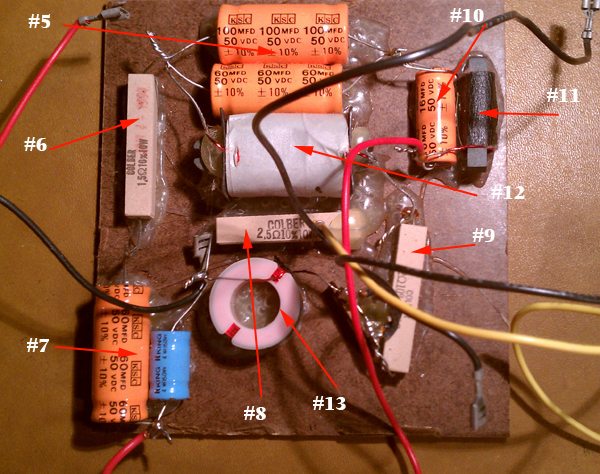
So now I know that #6, #8 and #9 are resistors and I don't have to do anything to them.
The caps here are #5, which like the example above is a 100 mfd plus a 60 mfd and I have a 100+50+10 that can go together as shown above
#7 is a 60 mfd and a 4 mfd and I have a 50, a 10 and a 4 for that one.
#10 is a 16, and I've got a 15+1 for that.
So what is #11 that's wired with the other 50 mfd cap?
I just got the upper crossover out, and here's what it looks like
So now I know that #6, #8 and #9 are resistors and I don't have to do anything to them.
The caps here are #5, which like the example above is a 100 mfd plus a 60 mfd and I have a 100+50+10 that can go together as shown above
#7 is a 60 mfd and a 4 mfd and I have a 50, a 10 and a 4 for that one.
#10 is a 16, and I've got a 15+1 for that.
So what is #11 that's wired with the other 50 mfd cap?
Last edited:
tromba
Super Member
As was mentioned in the first post, a very generous AK'er gave me these speakers along with the replacement caps. I have some other caps that looks completely different

You can probably read these, but they say "AUDIO GRADE" and larger ones say MPT 4.0uF, the smaller ones 0.1uF -- so are these really just 4 mfd and .1mfd?
Does AUDIO GRADE mean "better"?
You can probably read these, but they say "AUDIO GRADE" and larger ones say MPT 4.0uF, the smaller ones 0.1uF -- so are these really just 4 mfd and .1mfd?
Does AUDIO GRADE mean "better"?
Andy_H
Behind the Wall of Sleep
#11 is an iron core inductor. It doesn't need to be replaced. The Dayton caps pictured are indeed 4.0 and 0.1 microfarad - uF, MFD, µF are all ways of saying the same thing. "Audio Grade" isn't really any specific measurement, it's more of a manufacturer's marketing thing like a product labeled "Heavy Duty" or "Long-Lasting". These Dayton film caps you have are an affordable, good quality capacitor, a good choice for speaker crossovers.
tromba
Super Member
Do you mean the ones a post or two back with the yellow ends (message 24), or the ones at the top if this page (message 21)?These Dayton film caps you have are an affordable, good quality capacitor, a good choice for speaker crossovers.

Sir.Byrd
Lunatic Member
Do you mean the ones a post or two back with the yellow ends (message 24), or the ones at the top if this page (message 21)?
Yes.
Those are Dayton caps, usually you get those from partsexpress.
They have 5% tolerance and are film instead of electrolytic. They have a 250V rating, and that is inherent of film caps of this type.
Save the .1uF for an electrolytic cap that is directly in line (read: in series) with a driver, if you don't replace all of the old caps with film caps, that is.

Andy_H
Behind the Wall of Sleep
Do you mean the ones a post or two back with the yellow ends (message 24), or the ones at the top if this page (message 21)?
Post 24.

tromba
Super Member
Need reassurance
I'm pretty sure this is right, but I could use some reassurance before I actually heat up the soldering iron!!
as shown, the original caps are a 100uf and a 60uf. My replacements are a 100uf, a 50uf and a 10uf -- and they are just wired together on the ends as shown, correct?
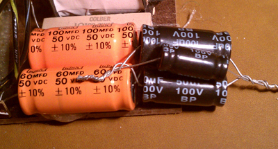
I'm pretty sure this is right, but I could use some reassurance before I actually heat up the soldering iron!!
as shown, the original caps are a 100uf and a 60uf. My replacements are a 100uf, a 50uf and a 10uf -- and they are just wired together on the ends as shown, correct?
Last edited:

NOHDjunkie
Well-Known Member
I'm pretty sure this is right, but I could use some reassurance before I actually heat up the soldering iron!!
as shown, the original caps are a 100uf and a 60uf. My replacements are a 100uf, a 50uf and a 10uf -- and they are just wired together on the ends as shown, correct?

Yes this is correct. Wired in parallel. Since you're going through the trouble of recapping, you might consider using Dayton poly caps instead of those electrolytics.

tromba
Super Member
The reason I have these is because they came with the speakers so I didn't have to "know" anything about purchasing. Since I haven't actually soldered yet, I'll look into this.Since you're going through the trouble of recapping, you might consider using Dayton poly caps instead of those electrolytics.
I just went to Parts-Express and found all kinds of Dayton poly caps.... (Plus LOTS of other brands....) What should I look at?
Dayton Metallized Polypropylene
Dayton Metallized 1% Polypropylene
Dayton Film and Foil Polypropylene
tromba
Super Member
Confused me on this.... isn't the 10uf a small one? I've got a need for 4 100uf...I would replace only the 10uF electrolytic in that stack with the 5% dayton film version.
It's in parallel with the woofer so you will get less benefits going all film here, plus, that would be huge and expensive.
I just priced them all out and if I'm looking at the right stuff this comes to about $236
I know these last longer but how about sound?
Last edited:
Sir.Byrd
Lunatic Member
Confused me on this.... isn't the 10uf a small one? I've got a need for 4 100uf...
I just priced them all out and if I'm looking at the right stuff this comes to about $236
I know these last longer but how about sound?
The original is a 100uF and 60uF.
You have new electrolytics of 100uF, 50uF and 10uF, totaling 160uf.
Just replace the 10uF with film, it will essentially be a bypass capacitor and improve the sound most of the way, with far less cost and size.
Do the rest of the caps that are not in parallel with the drivers in film, and get electrolytics for parallel values.
tromba
Super Member
Now I understand.... use the ones I already have for the 100uf and the 50uf, and just get the 10uf with film.The original is a 100uF and 60uF.
You have new electrolytics of 100uF, 50uF and 10uF, totaling 160uf.
Just replace the 10uF with film,
For the 64uf's, use the 60uf I have and get a film 4uf, and for the 16uf's, use the 15uf I have and a film 1uf! Or do I do this JUST with the woofer one on the 160uf ones. If that's the case, should I still use all film on the crossover for the tweeter?
I understand doing that, but not fully the reason why...

Good work tromba!
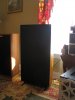
I purchased and refurbished a pair of A400 last fall. Re-foamed the woofers, re-built the bases, and replaced the grille clothe. Pics attached. I am impressed with the entire A-line form Boston Acoustics, and feel fortunate to own the A400. They are superb.
I thought about a recap at the time, but passed. I am very pleased with their sound, and decided to leave things be... at least for the time being. I think it is always difficult to decide on when to re-cap, and as you discovered there is a whole AK thread/debate on the topic. If you have not seen the A400 crossover schematic, AK member spkrdtr was kind enough to post a version (see post #23 in the thread) and there are also some very good reference photos from a_retent on an A400 re-cap in post #25: http://mail.audiokarma.org/forums/showthread.php?t=366910&page=2
Best of luck, and good listening!
(War Eagle!)
I purchased and refurbished a pair of A400 last fall. Re-foamed the woofers, re-built the bases, and replaced the grille clothe. Pics attached. I am impressed with the entire A-line form Boston Acoustics, and feel fortunate to own the A400. They are superb.
I thought about a recap at the time, but passed. I am very pleased with their sound, and decided to leave things be... at least for the time being. I think it is always difficult to decide on when to re-cap, and as you discovered there is a whole AK thread/debate on the topic. If you have not seen the A400 crossover schematic, AK member spkrdtr was kind enough to post a version (see post #23 in the thread) and there are also some very good reference photos from a_retent on an A400 re-cap in post #25: http://mail.audiokarma.org/forums/showthread.php?t=366910&page=2
Best of luck, and good listening!
(War Eagle!)
Attachments


Last edited: