• The move to the new server is done. There are some software and database maintenance updates in process. This has us passing the hat around to help out. We appreciate any donations. Seriously, even a dollar helps. The payment page may be found here - https://www.audiokarma.org/support.html

My First HH Scott LK-72 Restoration

richiem46

Retired and enjoying life and music!
Subscriber
I have restored about a dozen Fisher amplifiers of various types (KX-100, KX-200, 400, X202-B) and have enjoyed learning as I went with the help of folks on this forum. Folks here have a high regard for HH Scott equipment and I have been looking to acquire one to restore.
 
Register to hide this ad
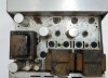
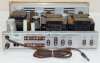
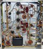
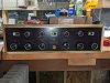
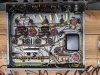
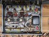
I recently acquired an LK-72 on the big auction site. It was pretty beat up and “untested” but the underside was clean and it had all of the tubes, the price was right so I took a chance and bought it. It was all original underneath except for a slight change in the bias network, R210 had a second 18-ohm resistor installed in parallel with it. I am attaching some pictures of it from the original sale listing.

LK-72-1.jpg LK-72-2.jpg LK-72-3.jpg LK-72-11.jpg LK-72-12.jpg
 
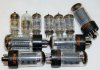
From the pictures alone you could see one of the 6GH8’s was DOA so I replaced both with 6U8’s that I had on-hand. I tested all of the remaining tubes and was happy that they all tested strong.
 
I connected speakers to the amp and an audio source into the “extra” inputs, plugged it into a variac and gradually applied A/C while checking B+ voltages. At about 100VAC the amp started to play weakly. B+ voltages were a bit off but not severely so. At 115VAC the unit still played weakly even at full volume so at that point I decided not to proceed further before re-capping the power supply and replace the selenium bridge rectifier in the Filament/Bias network and replace R210 with a 33-ohm resistor as previous restorers have recommended.
 
I ordered a re-cap kit from Hayseed Hamfest and while waiting for it to arrive I performed some chassis cleanup as well as the knobs and front panel. The panel has some paint loss around the loudness control but otherwise does not look too bad after cleaning. The chassis cleaned up somewhat but still will not win any beauty contests. The transformers are rusty, I am thinking about removing and painting them but hesitate as the wiring on the power transformer has cloth insulation, which was “crumbly” when I was working on the Bias supply. I will have to think about undertaking that a bit more.
 
The amp looks a lot better after some cleanup. Here are a few pictures I took of the unit after an initial cleaning. The chassis grime has largely been removed but there us still some corrosion left. The chassis lettering is very sensitive to any cleaning products it seems, perhaps because HH Scott used aluminum Chassis for their amplifiers. The front panel and knobs cleaned up pretty nicely.

PXL_20220609_201029589.jpg PXL_20220609_201049283.jpg PXL_20220609_201107084.jpg
 
When the Caps arrived I Installed them, starting with the Filament/Bias Cap. I also replaced the Selenium Bridge rectifier with a silicone bridge rectifier and substituted a 33-ohm resistor for R210. I powered up the amp at this point and it still played weakly. The bias voltage on the 7591’s was -49V, higher than the -45V indicated on the schematic. I then replaced the remaining three filter caps and then tested the amp again. Happily, it now played quite well and the B+ voltages were a little high but nothing alarming given 120V line voltage. The bias was still -49V, which I would need to adjust.
 
The next upgrades I decided to perform were to install 100-ohm screen stability resistors, which was straightforward. I also installed 10-ohm cathode resistors, which was a bit more interesting as the ground buss in the Scott amp tied into the output tube sockets at several points. I got that sorted out and now was able to measure the cathode current of each 7591 output. I powered up the amp and used the DC balance pots to balance both channels. Once balanced each 7591 was drawing 24MA of quiescent current. This was well below the recommended 35MA per 7591.

PXL_20220617_145653651.jpg
 
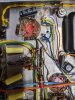
I reviewed the LK-72B schematic and decided to modify my LK-72 bias network to match the LK-72B’s configuration. I added the two 50K Bias pots, the 22K and 82K resistors and a 100Mf/100V electrolytic cap. I selected smaller pots as space was limited for their installation but by relocating a terminal strip I freed up enough space to drill holes and install the two new 50K bias pots. The chassis being aluminum was a blessing in this situation, making frilling the holes fairly easy. I powered up the amp after performing these modifications and was then able to bias each 7591 to 35MA easily. The amp played a bit stronger after re-biasing. Here is a picture of the installed components in the LK-72.
 

Attachments

  • PXL_20220617_145746360.jpg
    PXL_20220617_145746360.jpg
    158.6 KB · Views: 54
  • PXL_20220617_153003135.jpg
    PXL_20220617_153003135.jpg
    122.6 KB · Views: 54
I then replaced all of the white paper caps I found in the amp with IC film caps. Most of the caps I removed tested ok but one of the .022 caps on the loudness switch was open and after replacing that and the .015 caps on the Bass controls the amp definitely sounded better overall.
 

Attachments

  • PXL_20220617_145649602.jpg
    PXL_20220617_145649602.jpg
    197.9 KB · Views: 30
After finishing the restoration I was really pleased with how the LK-72 sounded, very solid and powerful. The sound is "different" than the Fishers that I have restored but very easy on the ears. I brought the amp indoors and hooked to up to my JBL E100B's and my Sony PSX-750 turntable to see how the amp sounded playing vintage vinyl. It played very nicely but to provide listenable volume I had to torn the loudness up to about 1PM to get good sound level. I again reviewed the LK-72 family of schematics and found that in the LK-72 a 100K resistor is in series with the RIAA (phono) input. In the LK-72B this is also true for the MAG-HI phono input but in the MAG-LOW input the 100K resistor is bypassed. This indicates the phono input of the LK-72 is MAG-HI. The tape input eliminates the 100K resistor in the LK-72 but the equalization would then be wrong.

I bypassed the 100K resistors tonight on the LK-72 and will test it tomorrow with the phono input and post my results then.
 
Nice, one step at a time. I have brought several Scott Integrated Stereo amplifiers back from the dead. Mixed results from electrolytic capacitors "reforming". Some do; some do not.

Nice job.
 
A Father's day update, I hooked the LK-72 to the turntable and speakers after installing the 100K resistor jumpers. The LK-72 now plays really well now with the turntable. 11AM volume setting is plenty loud now, I am even more pleased with the amp now. I swapped in a Fisher X202-B for a comparison and they are (very) subtly different in tone but both play beautifully. Not a bad dilemma to have to decide.
 
Back
Top Bottom