• The move to the new server is done. There are some software and database maintenance updates in process. This has us passing the hat around to help out. We appreciate any donations. Seriously, even a dollar helps. The payment page may be found here - https://www.audiokarma.org/support.html

My new HH Scott 299

rickl

I'm just a bass player
Subscriber
I picked up a Scott 299 recently. Missing all 12ax7 tubes, one 7189 and a 5AR4 tube.

Looks like it is a 299; not a A, B, C, or D. Serial number 40812.

I did find some NOS 6BL8 tubes in my stash. I plan to clean it up, replace or bypass the PS caps, add fresh coupling caps and get it working. I haven't removed the bottom cover to see if there is a selenium rectifier diode but if so, i'll replace with a 1n400x something and dropping resistor if needed.

if I can't find some 7189 tubes, can I use my pile of el84 tubes?

feel free to give feedback.
 
Last edited:
Register to hide this ad
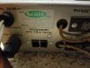
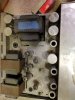
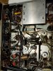
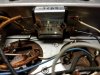
A few pics
 

Attachments

  • 20200710_144623.jpg
    20200710_144623.jpg
    96.1 KB · Views: 116
  • 20200710_145413.jpg
    20200710_145413.jpg
    72.5 KB · Views: 107
  • 20200710_144612.jpg
    20200710_144612.jpg
    101.9 KB · Views: 112
decided to remove the bottom cover. Found the tube chart and bridge for bias

20200710_150321.jpg
20200710_150410.jpg
20200710_150747.jpg
 
Last edited:
I found a schematic and with 360v on the 7189 plates, this might be too much for my el84/6bq5 stash.
 
Your first post says 7591’s. I assume you meant 7189’s. In any event, the 7189 is rated for higher plate voltage than the el-84. So, you can safely replace an el-84 with a 7189, but you cannot replace a 7189 with an el-84.
 
My 222C is running EL84s without a problem. Not an ideal situation but the tubes won’t fry.
 
Have been informed that EL84M’s are the way to go for tube life.

I’m sure those with experience will chime in....

Nice find,
Andy
 
Have been informed that EL84M’s are the way to go for tube life.

I’m sure those with experience will chime in....

Nice find,
Andy

The Mullard will work as will the Russian 6P14P-EV. They're extremely rugged and very good sounding as well as plentiful.
 
I picked up a Scott 299 recently. Missing all 12ax7 tubes, one 7189 and a 5AR4 tube.

Looks like it is a 299; not a A, B, C, or D. Serial number 40812.

I did find some NOS 6BL8 tubes in my stash. I plan to clean it up, replace or bypass the PS caps, add fresh coupling caps and get it working. I haven't removed the bottom cover to see if there is a selenium rectifier diode but if so, i'll replace with a 1n400x something and dropping resistor if needed.
Actually Scott never labelled any of these with an A, the early versions were just labelled 299 although some people call them a 299A.

There were actually two versions of the 299 before they came out with the 299B. One, like yours, has the OTs arranged left to right across the back. The other, which I believe was the earlier one, has the OTs on the left side front to back.

Unless you have the ability to test the PS caps for capacitance, leakage at working voltage and ESR you should plan on replacing them.

When I replace them I prefer to put individual caps underneath. The other option is to replace the can but that costs much, much more and the specs of typical replacement cans are not anywhere near as good as individual caps. You can leave the original can in place for looks but it should be disconnected not bypassed with additional new caps in parallel.

If you do have the ability to test the PS caps fully there's a chance they can be used. I have found some vintage can caps that test in spec for their listed capacitance and, when tested on a cap checker at full rated voltage they do not show any (electrical) leakage. When I find such a can my next step is to test it for ESR and compare the reading with a new replacement cap's ESR. Sometimes they are just as good as the new cap and I've even had some test better than the new cap. In those cases I will leave them in place but, of course, there's no guarantee how long they will continue to work well.
 
I found a schematic and with 360v on the 7189 plates, this might be too much for my el84/6bq5 stash.
In any event, the 7189 is rated for higher plate voltage than the el-84. So, you can safely replace an el-84 with a 7189, but you cannot replace a 7189 with an el-84.
Voltage is not the whole story. The more important issue is dissipation which is determined by the voltage (measured from plate to cathode) multiplied by the current.

The confusion and misinformation about the ratings of this "family" of tubes is due to the fact that some data sheets use the Design Center method and others use the Design Maximum method. The Design Maximum system results in ratings that are 10% higher.

For instance, when measured under the Design Center method, both the 7189 and the 6BQ5 have a Plate Dissipation of 12w, while the rating under the Design Maximum is 13.2w (10% higher).

The 7189 and 7189A variants are generally considered superior to the humble 6BQ5 because of the higher voltage ratings but the dissipation is the same. So - if you follow the data sheet specs - you can run higher voltages with the 7189s but you have to run it at lower current so you don't violate the 12w (13.2w) dissipation limit.

I've never been able to figure out why the voltage spec is higher for the 7189. Is there a difference in construction (materials or techniques) that would account for the 7189 having a higher plate voltage spec, yet at the same time, all the other specs (screen voltage, plate and screen dissipation) are exactly the same as the more common 6BQ5?

Interestingly, if you look at the various versions of another tube - 6L6G, 6L6GB, 6L6GC - the plate voltage specs get progressively higher BUT so do all the other specs (screen voltage, plate and screen dissipation).

This makes me wonder if "Uncle Ned", the former owner of Triode Electronics, may have been correct when he claimed that the 6BQ5 and 7189 were exactly the same tube.

I've also seen claims that the 7189A can be run harder than the 7189. Here's a link to the Sylvania data sheet that lists data for both 7189 and 7189A with both tested under the Design Maximum method. Specs are exactly the same. The only difference is that the pins are connected differently.

https://tubedata.altanatubes.com.br/sheets/106/7/7189.pdf

The 7189A can be used in place of a 6BQ5 or 7189 but only if pins 1, 6 and 8 are not connected to anything (or not used as tie points, for instance) because it has internal connections on those pins.

And then there are the Russian versions. The military versions of the 6P14P (-EV and -EB) and the EL84M are often said to be 7189 equivalents. They are supposedly "ruggedized" to be less susceptible to vibration and will supposedly last longer than the regular 6P14P. There do not seem to be any factory data sheets available for them.

I did find the data sheet for the Russian 6P14P. This is their version of the 6BQ5. It lists maximum plate dissipation at 14w vs 12w for the 6BQ5, 7189 etc. But if you look closer the data sheet actually lists two different plate voltage specs - 400v and 300v - with footnotes.

The footnotes say 400v is OK when plate dissipation is 8w or less but that the max is 300v when plate dissipation is over 8w. So, despite claiming a higher dissipation spec, it should be operated at 300v if you're going to be running anywhere close to that level of dissipation.

The Russian tubes have no connections on pins 1, 6 or 8 so they can be used in any amp designed for 6BQ5, 7189 or 7189A.

Personally, I have no experience with new production tubes but I've read enough stories about early failures that I don't trust that they actually meet the same specs as the data sheets that were developed by testing what are now old stock tubes.

Bottom line, if you use new production you might want to run them more conservatively. Buying the right to label a new production tube with a famous brand from the past is purely a marketing strategy designed to fool unsuspecting buyers.

 
you should plan on replacing them.

When I replace them I prefer to put individual caps underneath.

This is my plan. I've done this with many other restos with success.

I do have a "cheap" cap tester with ESR but not at operation voltage. It uses a 9v battery. It is nice for testing transistors and does measure capacitance and ESR but no idea how accurate it is. I like to use it as a pass/fail instrument.

Thanks for your great posts. I find this very useful. While I've been building/restoring tube amps since the 80s it is always great to brush up on a few things.
 
Just a follow up.

power switch is bypassed. It must be broken. The two 330R/10W resistors have been replaced with 160 20W sand power resistor. I guess someone has been in this amp before.

I got 7189 tubes from Jim McShane. sockets seem a little loose so I might need to fix that.

I replaced the bias rectifier with a bridge. Replaced the 10R/2W (R106) with a 22R/3W power resistor to help with the bias voltage. I got the bias and 12ax7 heater voltages closer to the schematic.

Slowly updating the coupling caps and can caps.
 
I've been using a set of JJ EL84 tubes in my 299A since 2001 without incident. They work fine.

Recapping these units with underchassis caps for the cans will be quite a challenge. There is very little space under the hood.
 
I do have a "cheap" cap tester with ESR but not at operation voltage. It uses a 9v battery. It is nice for testing transistors and does measure capacitance and ESR but no idea how accurate it is. I like to use it as a pass/fail instrument.
ESR meters don't test caps when they are charged as it will damage the meter.

The cap tester I mentioned, an old Eico that I rebuilt, works well for testing for leakage at working voltages. I also used it to test the capacitance value of electrolytics since my old meter didn't like them for some reason. The Eico's capacitance readings were very much approximate, but useful. I got a new Klein MM700 multimeter that works with lytics, so the Eico is only used for leakage testing now.

I just got one of those little 9v powered testers. They are really neat and incredibly cheap - the bare board was about $6 shipped. I mounted it in a little tin box. It's really versatile and seems to be very accurate.

My old ESR tester has an analog meter and I always questioned its accuracy. I used it mostly as an A/B tester to compare an old cap with a new replacement candidate. Never paid any attention to the actual reading. I should compare it to the new one sometime, I suppose.
Just a follow up. I replaced the bias rectifier with a bridge. Replaced the 10R/2W (R106) with a 22R/3W power resistor to help with the bias voltage. I got the bias and 12ax7 heater voltages closer to the schematic.

Slowly updating the coupling caps and can caps.
While you could probably skip the leakage test and use an old cap as long as there is no hum (which would be a sign of leakage) and if the capacitance is in spec and the ESR is similar to a new cap, a new one will have better specs and provide peace of mind.

If you haven't done so already, you might add a CL80 thermistor to the primary of the PT. It will provide a slightly more gentle start to the heaters and other secondaries and will drop a bit of voltage even after everything comes up. Equivalent to knocking the AC from the wall down by maybe 2v so it might help with heater voltages.
 
Eyou might add a CL80 thermistor to the primary of the PT

I actually added a CL80 to each primary leg of the PT. I use thermistors in all tube restores. I should have mentioned it. Always good to ask. Thanks!

I think the slow start up is more important than the voltage drop.
 
I think the slow start up is more important than the voltage drop.
They provide a bit slower and gentler start but not nearly as slow as the 5AR4 (or any other indirectly heated rectifier) does on the high voltage section. Everything helps though and the voltage reduction is a nice side effect.

If heater voltage is still off by much I just add a very low value (fraction of an ohm, usually 5w) resistor or two.
 
I was able to get the grids to -11v for each output (pin 2) and balanced using the DC balance pot.

What is the AC balance used for and should I adjust it? All I have is a scope, a few function generators, and volt meters. If this needs more instruments, I might leave it alone.
 
Back
Top Bottom