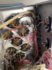
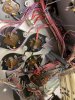
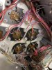
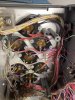
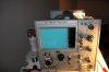
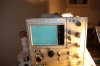
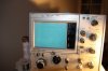
I was soooo jealous of all these guys like Tony X-Ray, Zenwizard, Alan Wolke (W2AEW), and more on Youtube. and their Tek 576.
So I decided to bring one back during my next US trip....from Belgium.
Finally a trip was planned to Phoenix in October. I found a 576 on Ebay for $525 - parts only unit. I did not want to pay too much as the overall risk of ending up with a boat anchor. took me a week to decide yes, no, yesssss, nooooo, ???? ..
..
Finally on Thursday night in my bed, with wife already asleep - did not want her to know , I decided to buy it - I only live once and its only money
 and my birthday is soon, ...in 8 months, ... xmas is closer.
I also had to keep the shipping costs down ==> I would have to take it a checked luggage on my flight back. Otherwise, I would have to pay several hundred bucks on shipping from US to Belgium + huge customs costs as customs would take a look and estimate the price based on google search ==> several thousand dollars ==> high import duties. But weight in the US was 80 pounds with the packaging.
So I had to reduce the weight ==> I looked at youtube videos from Zenwizard and came to the conclusion that the collector HV transformer had to be removed. so I took all the required tools with me.
The 576 has 4 transformers ( Main, collector HV, CRT HV, variac).
The 576 arrived as planned to my hotel. perfect box size, it fit the airline guidelines.
The first topic to solve was the weight - max is 70 pounds. the Unit + box was about 80 pounds.
Step 1 - Play
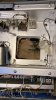
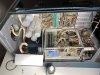
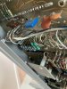
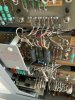
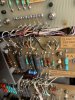
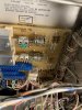
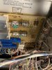
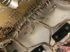
Play around with the unit and see what works .... nothing worked. one the relays inside did not stop buzzing.
some of the rail voltages where present.
Good news was that I had a later model with the black very HV transformer for the CRT.
But no trace ....
Step 2 - work to lose weight
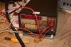
Get the collector HV transformer out - about 10 pounds (5kg) and the variac - another few pounds.
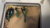
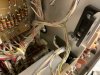
I couldn't access the transformer leads, as anticipated, with a soldering iron ==> I had to cut them off....
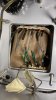
the HV transformer. the idea was that the transformer would just drop out... took me 2 hours to get it out.
I realized my later that there was a much better and elegant solution ... but that comes later.
Step 3 - get ready
Repack and make it easy for the luggage staff to carry the box, not break their back and not drop the box
  .
.
So I went to a hardware store to buy duct tape and some rope.
Closed the box, the unit had been foam packed so perfect box fit and no wiggle room in the box.
wrapped the rope around the box and made some kind handles with it.
Boxed weighed about 65 pounds on the hotel's dodgy weighing scale.
Step 4 - check
Make sure airline accepts it - so I went to airport the day before to check- they weighed it ... 69 pounds .
.
Step 5 - go
Next day 10 am I arrive at the airport. they did not even weigh the box...off it went .
.
Now I could only hope for the best - 3 legs (Phoenix-Denver- Munich-Brussels) - I bought some perfume on the way back
Step 6 - Pray
At every boarding I could see my box... the rope was all over the place, no more handles...
Step 7 - arrival at Brussels airport
The box was so unusual that I had to get it from the luggage claims desk... had to wait 15 min for them to get it... it finally arrived - and....
.
.
.
.
.
.
.
.
no damage to the box - so far so good
Step 8 - customs
how was I going to go thru customs
option 1 go to items the declare path and tell them I had nothing to declare - after all the unit was not working and parts were out - so no commercial value. but other course there was the risk they might not accept
Option 2: just walk out, with a straight face and hope for the best. with risk the officer stop me, then I would have to explain , and if they don't accept pay a fine on top of the import tax.
I opted for option 2 - sweating a bit for those 20 or so meter walking past the officer
step 9 - drive home
really.... issue at almost every step - the taxi driver refused to take the box
so I had to order a Uber van....any I got home after 20+ hours
Step 10 - the wife
 - "what the hell did you buy this time". I gave her the perfume
US TSA had cut the box open to check and had cut the rope (will know for next time)- they closed it put really well with tape- great girls/guys
Any way the baby made it home w/o damage .
.
Next steps - bring it back to life...
So I decided to bring one back during my next US trip....from Belgium.
Finally a trip was planned to Phoenix in October. I found a 576 on Ebay for $525 - parts only unit. I did not want to pay too much as the overall risk of ending up with a boat anchor. took me a week to decide yes, no, yesssss, nooooo, ????
..Finally on Thursday night in my bed, with wife already asleep - did not want her to know
, I decided to buy it - I only live once and its only money and my birthday is soon, ...in 8 months, ... xmas is closer.I also had to keep the shipping costs down ==> I would have to take it a checked luggage on my flight back. Otherwise, I would have to pay several hundred bucks on shipping from US to Belgium + huge customs costs as customs would take a look and estimate the price based on google search ==> several thousand dollars ==> high import duties. But weight in the US was 80 pounds with the packaging.
So I had to reduce the weight ==> I looked at youtube videos from Zenwizard and came to the conclusion that the collector HV transformer had to be removed. so I took all the required tools with me.
The 576 has 4 transformers ( Main, collector HV, CRT HV, variac).
The 576 arrived as planned to my hotel. perfect box size, it fit the airline guidelines.
The first topic to solve was the weight - max is 70 pounds. the Unit + box was about 80 pounds.
Step 1 - Play
Play around with the unit and see what works .... nothing worked. one the relays inside did not stop buzzing.
some of the rail voltages where present.
Good news was that I had a later model with the black very HV transformer for the CRT.
But no trace ....
Step 2 - work to lose weight
Get the collector HV transformer out - about 10 pounds (5kg) and the variac - another few pounds.
I couldn't access the transformer leads, as anticipated, with a soldering iron ==> I had to cut them off....
the HV transformer. the idea was that the transformer would just drop out... took me 2 hours to get it out.
I realized my later that there was a much better and elegant solution ... but that comes later.
Step 3 - get ready
Repack and make it easy for the luggage staff to carry the box, not break their back
and not drop the box .So I went to a hardware store to buy duct tape and some rope.
Closed the box, the unit had been foam packed so perfect box fit and no wiggle room in the box.
wrapped the rope around the box and made some kind handles with it.
Boxed weighed about 65 pounds on the hotel's dodgy weighing scale.
Step 4 - check
Make sure airline accepts it - so I went to airport the day before to check- they weighed it ... 69 pounds
.Step 5 - go
Next day 10 am I arrive at the airport. they did not even weigh the box...off it went
.Now I could only hope for the best - 3 legs (Phoenix-Denver- Munich-Brussels) - I bought some perfume on the way back
Step 6 - Pray
At every boarding I could see my box... the rope was all over the place, no more handles...
Step 7 - arrival at Brussels airport
The box was so unusual that I had to get it from the luggage claims desk... had to wait 15 min for them to get it... it finally arrived - and....
.
.
.
.
.
.
.
.
no damage to the box
- so far so goodStep 8 - customs
how was I going to go thru customs
option 1 go to items the declare path and tell them I had nothing to declare - after all the unit was not working and parts were out - so no commercial value. but other course there was the risk they might not accept
Option 2: just walk out, with a straight face and hope for the best. with risk the officer stop me, then I would have to explain , and if they don't accept pay a fine on top of the import tax.
I opted for option 2 - sweating a bit for those 20 or so meter walking past the officer
step 9 - drive home
really.... issue at almost every step - the taxi driver refused to take the box
so I had to order a Uber van....any I got home after 20+ hours
Step 10 - the wife
- "what the hell did you buy this time". I gave her the perfumeUS TSA had cut the box open to check and had cut the rope (will know for next time)- they closed it put really well with tape- great girls/guys
Any way the baby made it home w/o damage
.Next steps - bring it back to life...
Attachments



Last edited: