• The move to the new server is done. There are some software and database maintenance updates in process. This has us passing the hat around to help out. We appreciate any donations. Seriously, even a dollar helps. The payment page may be found here - https://www.audiokarma.org/support.html

My SA-9500II is blowing fuses, dear God, please help....

NOT the silver :yikes: - conductive is BAAAAADDDDDD..... don't trust some counter person on commission...

edit: no power - fireworks are likely - a good solid short that will blow main rectifiers and maybe transformers before the fuse gives up the ghost - IT'S function is not to save the electronics, but rather to keep from burning down the house.

Squeeze it down, it WILL conduct. The stuff is used between CPU's and heat sinks, where electrical conductivity isn't a factor. Don't gamble.

I use a carbon paint to restore remote keypads - same idea, conductive particles in suspension... silver is a BETTER conductor than copper - during WWII, magnets for the Manhattan project were wound in silver wire because of the copper shortages and the amount needed. Figured they could put it to better use than sitting in a vault somewhere.....

I didn't expect you to get thermal compound so quickly.

The Ceramic stuff is what you need if you just don't get plain old thermal compound. In my opinion, the more expensive thermal compound is akin to Radio Shacks Deoxit kit, just an excuse to stick a vacuum into your wallet.


The PNP and NPN transistor cases are opposite polarity, connected to the big capacitors - lots of voltage and plenty of amps to do damage.

markthefixer said:
The "big" output transistors are socket mounted on the heat sink, with a white goop (looks like sunscreen - and it's CLOSE, zinc oxide and silicon grease) that may disguise the thin, clear, FRAGILE sheets of mica insulator between the transistor and the heat sink. These insulators keep fireworks from happening. You will need new grease when putting it back together.

The metal parts of the output transistor are connected to the transistor's collector - which is DIRECTLY connected to those big capacitors. At plus and minus 50 volts or so with LOTS of amps of current. You don't want to short these.... the screws in the sockets are used to connect the transistor's collector to the socket as well, so the screws cannot touch anything else.

The white stuff is to fill the 0.001" air gaps between the transistor case, the mica and the heat sink.

We want to remove the heat without conducting electricity.

BUT

OTHER than the choice of thermal compound, everything else is spot on.

Make sure the same types (b to b, d to d) go into the same position, that was part of keeping track of where everything came from.

I would suggest doing an ohmmeter check to the heat sink from every transistor lead to look for shorts. There is a trick to that: start with verifying your heat sink connection with one ohmmeter lead by measuring with the other lead to the heat sink as well, then don't move probe #1, occasionally going back to the heat sink with probe #2 to make sure #1 hasn't lost it's connection.

In other words you want to avoid "good" readings that are happening only because probe #1 slipped and lost contact with the heat sink.
 
Last edited:
NOT the silver :yikes: - conductive is BAAAAADDDDDD..... don't trust some counter person on commission...

edit: no power - fireworks are likely - a good solid short that will blow main rectifiers and maybe transformers before the fuse gives up the ghost - IT'S function is not to save the electronics, but rather to keep from burning down the house.

Squeeze it down, it WILL conduct. The stuff is used between CPU's and heat sinks, where electrical conductivity isn't a factor. Don't gamble.

I use a carbon paint to restore remote keypads - same idea, conductive particles in suspension... silver is a BETTER conductor than copper - during WWII, magnets for the Manhattan project were wound in silver wire because of the copper shortages and the amount needed. Figured they could put it to better use than sitting in a vault somewhere.....

I didn't expect you to get thermal compound so quickly.

The Ceramic stuff is what you need if you just don't get plain old thermal compound. In my opinion, the more expensive thermal compound is akin to Radio Shacks Deoxit kit, just an excuse to stick a vacuum into your wallet.


The PNP and NPN transistor cases are opposite polarity, connected to the big capacitors - lots of voltage and plenty of amps to do damage.


The white stuff is to fill the 0.001" air gaps between the transistor case, the mica and the heat sink.

We want to remove the heat without conducting electricity.

BUT

OTHER than the choice of thermal compound, everything else is spot on.

Make sure the same types (b to b, d to d) go into the same position, that was part of keeping track of where everything came from.

I would suggest doing an ohmmeter check to the heat sink from every transistor lead to look for shorts. There is a trick to that: start with verifying your heat sink connection with one ohmmeter lead by measuring with the other lead to the heat sink as well, then don't move probe #1, occasionally going back to the heat sink with probe #2 to make sure #1 hasn't lost it's connection.

In other words you want to avoid "good" readings that are happening only because probe #1 slipped and lost contact with the heat sink.

:banana::banana::banana: The "grease" has been removed and replaced! The amp is "singing" again! :banana::banana::banana:


Dear Mark,

I think what you have done for me, and do for others here is truly noble work. Had it not been for your altruistic offer and subsequent help, I would have been…. well, who knows? I do know I was unable to have my amp repaired, or able even ship it to a repairperson. Now thanks to you, I am able to listen again!


I’ll think of you fondly when I “listen” from now on.

Gratefully, Bill.
 

Attachments

  • IMG_3373.jpg
    IMG_3373.jpg
    50.3 KB · Views: 59
Last edited:
Well, I look at it as "one UP, one to go."

The rest I fully understand - more than you might think.

How about that link to the thread where I made the hold-downs? Did you see them, and how do you feel about your fabrication abilities? (edit: I provided the link at the end of post #10 in this thread)

Those Fairchild transistors mentioned above look like good candidates, or the On-semi (MJ15032,33)'s, or even the TIP41,2's - all are under a buck, so we're talking about 8 bucks (or less) plus about 6 bucks shipping for a new set for the other amp.

Toss in 16 metric screws, the hold down bars and solder lugs and that's the full disclosure package for getting #2 going again.

Plus there's no rush...
 
Last edited:
I have said it before and I don't mind saying it again.....Mark is one of the greatest assets to AK IMO! Mark has helped me on 3 Pioneer receivers and all three are performing extremely well.

Nice to know you got your amp singing again, BB. Congrats!
 
Here is a link to the thread with the pictures of the refit.

http://audiokarma.org/forums/showthread.php?t=98733

And I'm working on his sa-9500 right now - learning a few things about good, sensitive phono amps too along the way.

The recently posted (Thanks, Carve-it!!) tuning fork guides confirmed that Pioneer's expectations of leakage in conventional electrolytics was 0.03cv, while their NL (CE A NL) cap leakage expectations were 0.003cv.

UPW caps are 0.03cv, and UKL caps are 0.003cv (at about double the price, for 85 degree C only, no less).

Poly film caps also come in at 0.002cv, as do tantalum caps.
Thus tantalum caps seem to be best replaced by low leakage UKL's when they were used in electrically sensitive applications, as opposed to space constrained locations.
 
I have said it before and I don't mind saying it again.....Mark is one of the greatest assets to AK IMO! Mark has helped me on 3 Pioneer receivers and all three are performing extremely well.

Nice to know you got your amp singing again, BB. Congrats!


Thanks for your words, pioneervato!
 
Terrified to hook up DIY speakers!

Hello guy's, Ive been through the speakers with a fine tooth comb and I cant find anything "new" or out of sorts with them. What is the minimum resistance this amp will tolorate? I get 6.6 ohms on the speakers with my fluke meter, but there are caps inline in the crossovers so Im not sure what resistance the amp "see's". If it "see's' only 6.6 ohms and needs to see 8 ohms, what value resistor should I place inline with the speakers to achieve 8 ohms?

Bill.
 
Hello guy's, Ive been through the speakers with a fine tooth comb and I cant find anything "new" or out of sorts with them. What is the minimum resistance this amp will tolorate? I get 6.6 ohms on the speakers with my fluke meter, but there are caps inline in the crossovers so Im not sure what resistance the amp "see's". If it "see's' only 6.6 ohms and needs to see 8 ohms, what value resistor should I place inline with the speakers to achieve 8 ohms?

Bill.

First check the speaker cables for intermittent shorts, then the crossover and drivers for intermittent shorts.

Are you sure the speakers sounded balanced - just because there's no DC short doesn't mean that at some frequency the impedance doesn't drop to dangerously low levels.

popping the same channel on two amplifiers means there is a problem.

How would I find it?

Put an 8 ohm resistor in series with the speakers, set the amp to mono, and get some sort of frequency generator (software, shareware?) that you can control the frequency of as a signal source.

Then use the fluke on AC voltage to measure the AC voltage across each speaker as the frequency is swept from 20hz to 20khz (manually?)

compare the voltages at these many frequencies - the speakers are part of a voltage divider, with that 8 ohm resistor, and any drop in impedance will cause a huge voltage difference between the speakers

You will probably hear a large difference in the sound levels between the two speakers when you hit the right spot.

BUT REMEMBER, a crossover isn't perfect, the other drivers in the speaker will be putting out that tone to some degree as well, of course the short will eat up most of the energy - depriving it from the other drivers - the resistor is helping that effect - before that effect was what was popping one channel.

also the 8 ohm resistor will present a reasonable load to the amp even if the speaker is shorted out. It does have to have an appropriate wattage, and you shouldn't have to crank it to do this - 1 watt - but with the 8 ohm resistor - the volume control position WILL be higher for the same sound level in the room. You have to double the voltage to get the same number of watts to the speaker to generate the SPL.


so you COULD try just playing music WITH the 8 ohm resistors (one for each) and see if you can spot the "hole".
 
Last edited:
Thank you for your quick replies Mark!

I have installed the (8 Ohm-25 Watt) resistors in line with the speakers. I used a test tone CD (Andersound) to run through the frequencies (28 Hz – 17 KHz in 1/6 octave steps).

Neither my wife nor I could hear an SPL difference between the speakers at any frequency.

These crossovers are 2nd order Linkwitz-Riley with Zobel networks for each driver and fixed value L-Pad attenuation on the tweeters (if this makes any difference at all).

When you say to,

“Then use the fluke on AC voltage to measure the AC voltage across each speaker as the frequency is swept from 20hz to 20khz (manually?) Compare the voltages at these many frequencies - the speakers are part of a voltage divider, with that 8 ohm resistor, and any drop in impedance will cause a huge voltage difference between the speakers.”

Do you mean to log the results of the AC voltage across the speaker leads for each driver and then compare the results between the cabinets (left/right), or do you mean compare the voltage results from driver to driver in the same cabinet)?

Also, am I to move from driver to driver with the meter at the theoretical frequency crossover points during the sweep?

Bill.
 
My measuring points would have been the two terminals on the outside of each of the speakers. If you had two identical meters you wouldn't have to go from speaker to speaker, but accurate AC voltages at under 1 to 5 volts are notoriously hard to get consistent results from meter to meter - then there's also the frequency dependent characteristics.

I would have both of the speakers with their backs to me, and would probe one and then the other in real time, as opposed to writing down readings. as laeast the first pass.

With the levels from the cd being the same the readings should stay essentially constant.

Not hearing any differences surprises me. But at lower levels it may be harder to distinguish - I use a RS sound level meter, and use the balance control to shift from (side by side) speaker to speaker, that's how I found a bad mid crossover cap years ago, the difference was only 2 db by the meter as I got into the mid frequency band... before that I thought I was imagining things.

Another "trick" is to measure the voltage across the 8 ohm resistor instead, that will give you the current being drawn by the speaker. Or just put the meter inline with the speaker (keep the 8 ohm resistor connected to protect the amp) and read the current - the meter has a small shunt resistance it measures across.
We are assuming that the voltage output at the amplifier stays constant.

Just how well do you trust the cables being run to the speakers? Usually when channels blow without sustained room pounding volume levels, there was a short in the wiring - or some of those speakers that drop down to two ohms at some frequencies were connected..... and if the short or intermittent short is in the cable between the amp source side and the speakers, we're still putting the amp at risk.

Tell me about the cables, and what was done/connected - disconnected etc when each of the amps blew the same channel.
 
Last edited:
Ok, here we go..

Thanks again Mark!

I’ve done one of the tests you suggested, the readings fluctuated so I recorded the highest and lowest readings presented.

The following are the A/C voltage testing results across the resistor, using a Fluke 73 Multi-Meter:

**EDIT*** Voltage test across SPEAKERS. SA-9500II volume selector set @ -34DB.


Frequency (Hz) Left (Voltage) Right (Voltage)
28 .3-1. .3-1
32 .4-1. .3-1.
36 .4-1. .3-1.
40 .4-1. .3-1.
45 .4-1. .2-1.
50 .4-1. .2-1.
56 .4-1. .3-.8
63 .3-.9 .3-.8
71 .3-.8 .3-.7
79 .3-.6 .3-.7
89 .3-.7 .2-.8
100 .2-.5 .2-.6
112 .2-.6 .2-.7
142 .3-.6 .2-.6
159 .3-.6 .3-.7
178 .2-.6 .2-.6
200 .3-.6 .2-.6
220 .3-.6 .3-.6
250 .3-.7 .3-.7
280 .3-.6 .3-.6
320 .4-.6 .3-.6
360 .3-.5 .3-.6
400 .2-.5 .3-.5
450 .3-.5 .3-.5
500 .3-.5 .3-.5
560 .3-.5 .3-.4
630 .3-.4 .3-.5
710 .3-.4 .3-.4
790 .3-.4 .3-.4
890 .3-.4 .3-.4
1K .3-.4 .3-.4
1K12 .3-.4 .3-.4
1K26 .3-.4 .3-.4
1K42 .3-.4 .3-.4
1K60 .3-.4 .3-.4
1K78 .3-.4 .3-.4
2K .3-.4 .3-.4
2K2 .3-.4 .3-.4
2K5 .3-.4 .3-.4
2K8 .3-.4 .3-.4
3K2 .3-.4 .3-.4
3K6 .3-.4 .3-.4
4K .3 .3
4K5 .3 .3
5K .3 .3
5K6 .2-.3 .2-.3
6K3 .2 .2
7K1 .2 .2
7K9 .2 .2
8K9 .1 .1
10K .1 .1
11K .1 .1
12K6 .1 .1
14K2 .1 .1
15K9 .08 .08
17K8 .07 .07

I’ve since gone through the crossovers, checking the resistor, capacitor and inductor values, everything checks out fine. I’m thinking I’ll order and replace the capacitors (in case of an intermittent short). I was also thinking I might increase the DC resistance of the speakers from 6.6 Ohms to 8 Ohms with some type of inline resistor, say around 1.5 Ohms.

What do you think I should do next?

Bill.

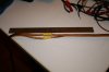
P.S. Here are some pics of the resistors and cabling.
 

Attachments

  • IMG_3374.jpg
    IMG_3374.jpg
    81.3 KB · Views: 40
  • IMG_3377.jpg
    IMG_3377.jpg
    34.8 KB · Views: 35
Last edited:
Well, both speakers are acting symmetrically, this was measured across the resistor, so the increased impedance of the speaker at higher frequencies is showing up as a reduced load on the amp.

At spot frequencies (say every 4 frequencies skipping three) take readings on just one channel, one across the resistor and one across the speaker, your last readings were just across the resistor. Leave the one voltmeter lead connected to the resistor - the heavy lead that goes to the speaker (the "center point"), and take two readings, one from that center point to the red terminal which will read across the resistor, the other one from that center point to the black terminal which will read across the speaker.

WE have one unassailable and irreconcilable fact here - blown amp channels.... Have you inspected the entire length of the spliced cable minutely - for insulation damage or evidence of chewing? And compared them side by side?
 
Last edited:
A question...

Hello Mark,

When you wrote, “Well, both speakers are acting symmetrically, this was measured across the resistor.” I want to be sure I understood your direction. Firstly, I placed the resistor inline on the positive speaker cable. Secondly, I Placed the black lead on the negative speaker line and the red lead to the resistor (between the resistor and the speaker cabinet, Not between the amp and the resistor) was this the correct way to run the test I ran?

Bill.
 
Last edited:
Hello Mark,

When you wrote, “Well, both speakers are acting symmetrically, this was measured across the resistor.” I want to be sure I understood your direction. Firstly, I placed the resistor inline on the positive speaker cable. Secondly, I Placed the black lead on the negative speaker line and the red lead to the resistor (between the resistor and the speaker cabinet, Not between the amp and the resistor) was this the correct way to run the test I ran?

Bill.

yes - I meant that both speakers were acting the same - I had expected the left? channel one (the side of the blown amp channel) to have different results - the further test was to see if they BOTH were on the verge of popping a channel and it was a coincidence that the same channel went first both times.

they looked good to me, thus my increased suspicions about the cables.

it seems unlikely that the zobel output filters on both amps would go out on the same channel.
 
I just finished re-reading this thread...great information and a lot to learn for a "young guy" like me :yes:. Bill, thanks for sharing the pain :tears: of loosing your music, makes me appreciate mine even more (this qualifies as the "You don't know what you've got 'til you lose it" moment!). I'm glad to hear that you've got one of the units up and running thanks to Mark. Mark, you are a treasure to this forum...my sincere thanks for willingly sharing your knowledge :thmbsp: on all of our electronic problems.
 
I also enjoyed reading this thread and others like it.

I've learned so much from AK and the experts like Mark who give so freely of their knowledge helping keep our beloved vintage gear running.

Thanks Big Bill for starting this thread as I hope to tear into my SA 9500 II this winter and this has been great to follow along and read the out come.
 
Back
Top Bottom