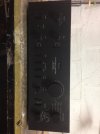
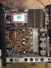
Hello everyone, in the mean time I introduce myself, I'm Aldo and I've been following this forum for some time, just since I regained the habit of listening to music properly and buying some amp;
I hope this is the right section to post my question.
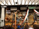
I have a problem with an amplifier that is driving me crazy; I've been in possession of a Sansui AU-D9 for 5 years now; when I left home I immediately turned it on and with great happiness I see that it worked, so I remove its wooden lid without even scratching, to give it a clean of the dust (not even much) and make the adjustments of the case; I immediately realize that After a few minutes it gave off a slight smell of burnt components but I don't notice anything burnt, so I start touching the transistors, to see the temperature and I notice that the low power transistors (Q19-Q20) are very hot, (around 80°); I check all the voltages BE and these are within limits; unfortunately, trying to make other measurements, I carelessly cause a short circuit and burn an A1169; after some time I replace all four transistors with new ones, but some prove to be fake and in addition to some resistance outside I also make C2238 and A968; since then I have put back The cover at the Sansui and it's been 5 years and three moves.... about a month ago I took the Sansui back in hand and tried to count the damage caused by the last ignition...... in short, resistors, transistors and final transistors; for the rest of the material I had no problems but for the 2SA196/2SC2773 pairing it seems that there is no hope of finding good ones, so I start looking for current transistors, in production and above all that are compatible.... found, even under the advice of a friend, the 2SC5200/2SA1943 coupling, I take them and put them on;
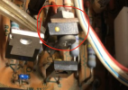
In my research I find several discussions about the damage that the famous "black flag" capacitors could cause, and my Sansui has many..... well, let's change those too, maybe they cause an auto oscillation to the transistors. Well, I have all the material and very calmly I carry out my work, once everything is mounted and checked well I proceed with turning on the amplifier using a Variac and the classic bulb in series and I start to pray; as I go up with the voltage I check that the voltages are within the range of the Service Manual, until I get to the working voltage, so far everything is ok. I remove the lamp and resume with the Variac until I get to the voltage of 225V, I leave the device with the volume at minimum and without rising and I start to make the DC and Bias adjustments, everything perfect, I'm about to do a power test with connected dummy load and 1kHz signal at 100mV; everything is fine until half of the volume burns a resistor (R39) and two final transistors; luckily I was doing the test only on one channel and therefore the damage is limited to only one channel, the left one. I have another pair of 5200/1943, I mount them and redo all the checks of the case, everything normal; this time I want to connect a pair of speakers instead of the fictitious load; music finally comes out of the speakers, and I leave everything working for about 30 minutes at volume, about 10 o'clock; then I connect the Sansui to a turntable and to my speakers at home, after about 15 minutes and a bang coming from inside the amplifier, everything stops, then no music comes out of my speakers, **** it will have happened again, I checked and rechecked everything several times before making it play. ok, the power transistors and the usual resistor burned out again, this time on the right channel;
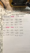
Today I finally get back on the Sansui and do some investigations, one thing I never noticed is that on the SM a voltage is reported, at the exit of the rectifier bridges, of 62.5V, but I measure about 55.7V;
The voltages here refers to the SM in the POWER AMP circuit are fine for one channel but in the other I have about 1V more;
Ultimately the machine turns on and works but as soon as the volume is turned up the ends burn;
Sorry for the very long place but I think it is necessary to know every aspect of the attempted repair;
I thank those who have had the patience to read everything to the end and those who will want to give me a hand;
Thank you
PS
My English is Goggle Translator made
I hope this is the right section to post my question.
I have a problem with an amplifier that is driving me crazy; I've been in possession of a Sansui AU-D9 for 5 years now; when I left home I immediately turned it on and with great happiness I see that it worked, so I remove its wooden lid without even scratching, to give it a clean of the dust (not even much) and make the adjustments of the case; I immediately realize that After a few minutes it gave off a slight smell of burnt components but I don't notice anything burnt, so I start touching the transistors, to see the temperature and I notice that the low power transistors (Q19-Q20) are very hot, (around 80°); I check all the voltages BE and these are within limits; unfortunately, trying to make other measurements, I carelessly cause a short circuit and burn an A1169; after some time I replace all four transistors with new ones, but some prove to be fake and in addition to some resistance outside I also make C2238 and A968; since then I have put back The cover at the Sansui and it's been 5 years and three moves.... about a month ago I took the Sansui back in hand and tried to count the damage caused by the last ignition...... in short, resistors, transistors and final transistors; for the rest of the material I had no problems but for the 2SA196/2SC2773 pairing it seems that there is no hope of finding good ones, so I start looking for current transistors, in production and above all that are compatible.... found, even under the advice of a friend, the 2SC5200/2SA1943 coupling, I take them and put them on;
In my research I find several discussions about the damage that the famous "black flag" capacitors could cause, and my Sansui has many..... well, let's change those too, maybe they cause an auto oscillation to the transistors. Well, I have all the material and very calmly I carry out my work, once everything is mounted and checked well I proceed with turning on the amplifier using a Variac and the classic bulb in series and I start to pray; as I go up with the voltage I check that the voltages are within the range of the Service Manual, until I get to the working voltage, so far everything is ok. I remove the lamp and resume with the Variac until I get to the voltage of 225V, I leave the device with the volume at minimum and without rising and I start to make the DC and Bias adjustments, everything perfect, I'm about to do a power test with connected dummy load and 1kHz signal at 100mV; everything is fine until half of the volume burns a resistor (R39) and two final transistors; luckily I was doing the test only on one channel and therefore the damage is limited to only one channel, the left one. I have another pair of 5200/1943, I mount them and redo all the checks of the case, everything normal; this time I want to connect a pair of speakers instead of the fictitious load; music finally comes out of the speakers, and I leave everything working for about 30 minutes at volume, about 10 o'clock; then I connect the Sansui to a turntable and to my speakers at home, after about 15 minutes and a bang coming from inside the amplifier, everything stops, then no music comes out of my speakers, **** it will have happened again, I checked and rechecked everything several times before making it play. ok, the power transistors and the usual resistor burned out again, this time on the right channel;
Today I finally get back on the Sansui and do some investigations, one thing I never noticed is that on the SM a voltage is reported, at the exit of the rectifier bridges, of 62.5V, but I measure about 55.7V;
The voltages here refers to the SM in the POWER AMP circuit are fine for one channel but in the other I have about 1V more;
Ultimately the machine turns on and works but as soon as the volume is turned up the ends burn;
Sorry for the very long place but I think it is necessary to know every aspect of the attempted repair;
I thank those who have had the patience to read everything to the end and those who will want to give me a hand;
Thank you
PS
My English is Goggle Translator made
Last edited: