• The move to the new server is done. There are some software and database maintenance updates in process. This has us passing the hat around to help out. We appreciate any donations. Seriously, even a dollar helps. The payment page may be found here - https://www.audiokarma.org/support.html

My Winter Project

Please put up schematics of what you've done. I am sitting by with great anticipation.

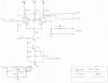
Will do Douglas, I'm do some doodling soon. I will tell you that I tested the 6CL6 long-tail pair with BJT CCS and achieved an output swing of about 150Vpp with less than 0.5% THD (my measurement limit). Single ended gain at the particular screen voltage, which I forget what it was, was 35 v/v. My one concern with this is if it will have enough gain to make the required input signal reasonable, but i do have an aikido preamp in the works which has plenty of excess gain. I did a little simulation before and I think i determined I needed about 15 volts peak input per grid for full power out. The EL34s are biased at -25v (about 25ma/tube), but don't need to be driven full to 0v for full output. So I THINK i'll have some excess gain for feedback, which the transformers have a dedicated winding for, which is sweet.

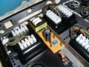
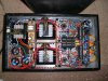
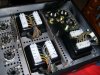
Little bit of wiring here, lead dress for the transformers, which will make it easier in the long run. Extra 70v winding too if I ever want to try cathode feedback. We'll see.
 

Attachments

  • lead dress - before.JPG
    lead dress - before.JPG
    187.1 KB · Views: 369
  • lead dress - after.JPG
    lead dress - after.JPG
    182.2 KB · Views: 324
Lookin' Good! I'm hoping to hear this before I leave ... probably would be done right now if not for my Bogen Jr. project diversion :D
 
Will do Douglas, I'm do some doodling soon. I will tell you that I tested the 6CL6 long-tail pair with BJT CCS and achieved an output swing of about 150Vpp with less than 0.5% THD (my measurement limit). Single ended gain at the particular screen voltage, which I forget what it was, was 35 v/v. My one concern with this is if it will have enough gain to make the required input signal reasonable, but i do have an aikido preamp in the works which has plenty of excess gain. I did a little simulation before and I think i determined I needed about 15 volts peak input per grid for full power out. The EL34s are biased at -25v (about 25ma/tube), but don't need to be driven full to 0v for full output. So I THINK i'll have some excess gain for feedback, which the transformers have a dedicated winding for, which is sweet.

Little bit of wiring here, lead dress for the transformers, which will make it easier in the long run. Extra 70v winding too if I ever want to try cathode feedback. We'll see.

Sounds sweet! When you're done with it, I would really like to hear it. Given your SE gain, you should not need much voltage at the input. Besides, at reasonable levels, you'll be far below that( but with PPP, no nead for reasonable eh? )

Nice to see that amp w/o the spiders and scratches, that is for sure...:)
cheers,
Douglas
 
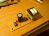
Negative voltage supply for CCS. Triad 3FD-324 transformer, 24V@0.1A.
 

Attachments

  • STP60490.JPG
    STP60490.JPG
    182.6 KB · Views: 249
  • STP60492.JPG
    STP60492.JPG
    180.1 KB · Views: 289
That buss is one thing I'll be paying close attention to. Am I right in thinking that you will keep the higher current devices down by the first cap and the signal stuff clear to the other end? BTW, a close up of the grounding would be cool.:smoke:
 
That buss is one thing I'll be paying close attention to. Am I right in thinking that you will keep the higher current devices down by the first cap and the signal stuff clear to the other end? BTW, a close up of the grounding would be cool.:smoke:

By fortune, all the high current stuff happens to be in one corner. Dem' bogen engineers were smart guys. The highest current stuff (aside from heaters) will be the peak currents in the voltage doubler power supply.

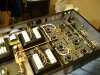
Just finished the heater supply for the E34Ls. I had to use heat-shrink to keep my twisted pairs, twisted. The beefy stranded teflon wire has a mind of its own. I'm waiting for smaller teflon wire in the mail before I connect the driver tubes. Just something about that stuff I love, especially after dealing with PVC for so many years. I also believe there is a law of physics or something that states that all solder fumes must travel towards iron operator's eyes and nose....
 

Attachments

  • STP60498.JPG
    STP60498.JPG
    184.7 KB · Views: 354
6CL6 plate resistors and E34L screen resistors are in. Power supply is pretty much finished, but waiting for NTCs in the mail.
 

Attachments

  • STP60503.JPG
    STP60503.JPG
    187.3 KB · Views: 359
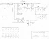
Drew up the power supply schematic. Should have the thing running today, making music at least.
 

Attachments

  • Power_Supply_fit.JPG
    Power_Supply_fit.JPG
    123.7 KB · Views: 300
She's making music!!

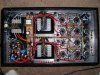
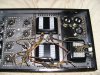
Here's a pic from late in the game. Solid state CCS board is in and caps tie-wrapped to ground bar.

Can't turn it up real loud tonight (neighbors), but will give better listening test tomorrow:thmbsp:
 

Attachments

  • STP60506.JPG
    STP60506.JPG
    188.8 KB · Views: 393
  • Driver_Stage_fit.JPG
    Driver_Stage_fit.JPG
    118.5 KB · Views: 185
Very cool!:thmbsp: I admire your lead dress. Everything looks well planned out and organized. Your use of the terminal strips really gave it a professional look. Can't wait to hear your listening impressions.:music:
 
She's making music!!

Here's a pic from late in the game. Solid state CCS board is in and caps tie-wrapped to ground bar.

Can't turn it up real loud tonight (neighbors), but will give better listening test tomorrow:thmbsp:


hey-Hey!!!,
Consider adding a cap between your cathode node and the wiper of your screen balance pot. Maybe two, one to each screen from the cathode.
cheers,
Douglas
 
hey-Hey!!!,
Consider adding a cap between your cathode node and the wiper of your screen balance pot. Maybe two, one to each screen from the cathode.
cheers,
Douglas

Funny you mention that. I had that initially in bench testing (when the <0.5% thd was quoted), but didn't install them in the unit yet. I wasn't sure if they were making any difference, I'll try them out soon.

I did some bandwidth tests at 1 watt, 5 watts, and 20 watts.

1 watt and 5 watt tests were pretty much the same at:
-1db @ 23Hz - 22KHz
-3dB @ 15Hz - 41KHz

20 watts:
-1dB @ 21Hz - 22KHz
-3dB @ 12Hz - 30KHz
The -3dB lower frequency limit measurement is affected by the core saturation distortion. It's higher if a undistorted wave is desired (Makes me wonder how manufacturers apply this measurement).

None of these are exact, I used my scope to measure. A precision AC voltmeter would be best. But, it does look pretty good nonetheless.

addition: Also did brief power test to see where crossover distortion was noticed = at about 25 watts.
and also, hum and noise with grounded input was below 8mV.
 
addition: Also did brief power test to see where crossover distortion was noticed = at about 25 watts.
and also, hum and noise with grounded input was below 8mV.

Not bad! You might never make it to 25W with your present speakers ;)

So have you applied any feedback yet? Any square wave attempts?

I'm excited; this amp went from Douglas' garage, to my basement, to "great success".
 
Not bad! You might never make it to 25W with your present speakers ;)

So have you applied any feedback yet? Any square wave attempts?

I'm excited; this amp went from Douglas' garage, to my basement, to "great success".

Those numbers were with feedback, no square waves yet, I shoulda done that while i had it hooked up, but I forgot.

Listening to it now, it does have bass like no other tube amp I have. VERY clear too.:thmbsp:
 
Those numbers were with feedback, no square waves yet, I shoulda done that while i had it hooked up, but I forgot.

Listening to it now, it does have bass like no other tube amp I have. VERY clear too.:thmbsp:
I wonder if those open baffle speakers might actually prefer the relatively high output impedance :scratch2:
 
Back
Top Bottom