• The move to the new server is done. There are some software and database maintenance updates in process. This has us passing the hat around to help out. We appreciate any donations. Seriously, even a dollar helps. The payment page may be found here - https://www.audiokarma.org/support.html

NAD 3020 Series 20 (late) idle current questions

Willarado

Active Member
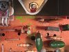
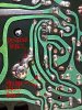
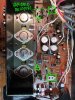
Hi, I'm a new member and just completed my first recap of an NAD 3020 that I bought new in 1982. This is a later version with the large caps in the center of board behind the heat sink. The recap seems to have gone well and startup and other noises have all disappeared. The amp sounds great though I haven't given a lot of listening time yet. My questions: is it 100% necessary to reset the idle current after a recap? At idle the transistors get warm but not hot. The DC offset is 28.4 mV left and 13.3 mV right. Are those acceptable numbers? Finally, if idle adjustment is necessary I plan to add the adjustable resistors per other threads I've seen here. However, I'm not clear if I am identifying the solder bridge correctly and where to measure across. I've attached a couple photos, does it look like I'm understanding this correctly? Thanks!
 

Attachments
  • IMG_7800.jpg
    IMG_7800.jpg
    176.8 KB · Views: 33
  • IMG_7801.jpg
    IMG_7801.jpg
    124.6 KB · Views: 35
  • IMG_7799.jpg
    IMG_7799.jpg
    158.5 KB · Views: 35
Last edited:
Register to hide this ad
Personally I'm making sure the ideling current is good after my recap.
I have my left channel set between 30-31mV but I am struggling getting a reading on the right channel... I have 1k trimmer solder there, I was wondering if you did the measument on your unit and how it went?

Thanks
 
Why take all the time to recap it, and not adjust the bias and offset? Replace the offset trimmers with some 20K Bournes multi-turn, measuring the ones you took out first. In your IMG_7801 picture above, replace one of those resistors with a 1K2, and the other with a 1K Bournes multi-turn set to 500 ohms. As you have in IMG_7799, remove the solder bridge, and measure across those two points. I would recommend soldering two scraps of wire to bring out the front of the amp, and clipping your meter leads onto those.

It should be relatively easy to get the offset down to as close to zero as possible. I just did an amp for a fellow AKer, and got within 0.3mV offset on both channels. Bias was set to 30mV.

Just looking at the pictures, did you remove the output transistors and re-grease them?
 
Why take all the time to recap it, and not adjust the bias and offset? Replace the offset trimmers with some 20K Bournes multi-turn, measuring the ones you took out first. In your IMG_7801 picture above, replace one of those resistors with a 1K2, and the other with a 1K Bournes multi-turn set to 500 ohms. As you have in IMG_7799, remove the solder bridge, and measure across those two points. I would recommend soldering two scraps of wire to bring out the front of the amp, and clipping your meter leads onto those.

It should be relatively easy to get the offset down to as close to zero as possible. I just did an amp for a fellow AKer, and got within 0.3mV offset on both channels. Bias was set to 30mV.

Just looking at the pictures, did you remove the output transistors and re-grease them?
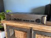
Thanks, this is the info I was hoping for back in November when I posted this. I'll open it up when I have time and make these adjustments and re-grease. It's fun to have this amp up and running again. And I still have the old rack handles :)IMG_7816 edited.jpg
 
Personally I'm making sure the ideling current is good after my recap.
I have my left channel set between 30-31mV but I am struggling getting a reading on the right channel... I have 1k trimmer solder there, I was wondering if you did the measument on your unit and how it went?

Thanks
I never got around to it, but I think I'll open it up again and get this done. Leesonic shared some good info here.
 
Back
Top Bottom