• The move to the new server is done. There are some software and database maintenance updates in process. This has us passing the hat around to help out. We appreciate any donations. Seriously, even a dollar helps. The payment page may be found here - https://www.audiokarma.org/support.html

Nad 3020a

GytisBal

New Member
Hello,

I have accured few problems with my NAD.
Firstly, when I turn the amplifier on, there is a Pop sound on speakers, or headphones (not loud, not terrible but still its exist).
Secondly, when i turn the amplifier on, there will be no sound for ~10 seconds. After that, sound would increase slowly, first on one side, when after 1-2 seconds on other side. After another additional 5-10 seconds sound will reach selected desired level of sound.

Thanks, for replies my friends
 
Register to hide this ad
As well, how to adjust idle current, now RX1/RX2 has pot installed, and set to default value R180.
So I need to install 1k resistor parrarel with R653/654, and measuring across that 1K ohm resistor?
And the value need to be 30-60mV?

Thanks for clear answer.
 
Update:
In place of R653/654 its seems that's installed 1 Ohm resistor (Brown Black Gold Gold)
So do i need to install 1 kOhm resistor pararell to this 1 ohm resistor, and measure on 1 kOhm? 30-60mV??
As well before measuring it, I need to unsolder bridge (which is red circled)?

RX1/RX2 is 180 Ohm, as was resistor intalled before

Need answer asap, please :)

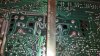
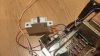
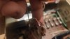
IMG_20201012_010349.jpg IMG_20201012_010410.jpg
 
Last edited:
I just finished up a 3020, I think it’s the same as yours. You do need to remove the solder bridge and measure across the bridge for 30-60 MV. I solder leads on both sides of the bridge and attach my dvm To the leads. It’s just easier. I can’t answer your question about resistor values, since I’m not at home, but I can help you latter tonight with them when I can check my 3020

The startup problem my be your power switch arcing. Mine does the delay at startup. But I don’t have the pop
 
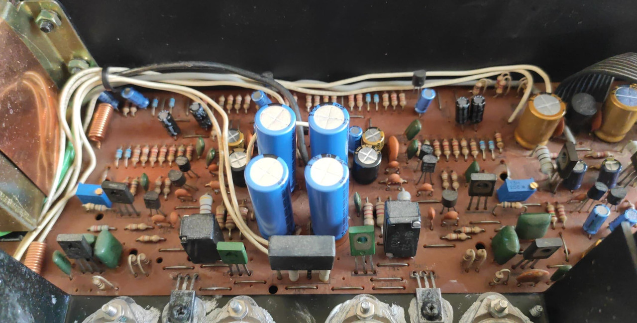
On later amps, the bias adjustment resistors (R645/646) are 180R, with a value set by the factory in parallel with them (RX1 and RX2). "Later" amps are the ones without the power supply board on the back, and the four caps in the center of the board. This also extends to A and B models, plus the 3120. I always swap out R645/646 with a 1K2 resistor, that makes the adjustment easier.
Lee.
Should i replace existing resistors with 1k2 Ohm ones next to pots? Or its not necesery?
Or i just replace these resistors with 1k2 ones. Desolder bridge, measuring it across it. While turned on and lowest volume. If mV ok, resolder bridge, and same on other side. Am I right?
 
Last edited:
The picture above shows a weird looking thermal compound on the output transistors. Is it silver? I'm wondering if whoever worked on the amp before used the thermal compound that is meant for CPUs and other computer chips. This is NOT the right stuff to use as it conducts electricity. I would get this fixed sooner rather than later.

As for the resistors. You need to measure across the 1 ohm resistor with the solder short removed. I would also use 1K2 resistors next to the pots, and start with the pots at least 500 ohms, and work downwards.

Lee.
 
The picture above shows a weird looking thermal compound on the output transistors. Is it silver? I'm wondering if whoever worked on the amp before used the thermal compound that is meant for CPUs and other computer chips. This is NOT the right stuff to use as it conducts electricity. I would get this fixed sooner rather than later.

As for the resistors. You need to measure across the 1 ohm resistor with the solder short removed. I would also use 1K2 resistors next to the pots, and start with the pots at least 500 ohms, and work downwards.

Lee.
Thanks, Lee :). Helped so much. Adjusted bias, thank you ;)

Cleaned power switch with contact cleaner, so now Pop is quiter :)
Only whats left is sound problem at begining, if it's not something dangerous, I'm keeping like that, will upload video, how it looks like.

 
I think (may be wrong) that this model has a soft startup mute circuit.
On the one I refurbished, which looks the same, upon turning on, no immediate sound, then the sound would “ramp up” to the set volume. This is probably some resistor capacitor delay that turns on a transistor in the preamp section.
So, either the resistor or capacitor is different between both sides, causing one side to come up to set volume before the other.
That’s my guess.

Mr Relish
 
I think (may be wrong) that this model has a soft startup mute circuit.
On the one I refurbished, which looks the same, upon turning on, no immediate sound, then the sound would “ramp up” to the set volume. This is probably some resistor capacitor delay that turns on a transistor in the preamp section.
So, either the resistor or capacitor is different between both sides, causing one side to come up to set volume before the other.
That’s my guess.

Mr Relish
Hmmm... i think i need a clear schematics. And some research i guess.
 
I think that model Series 20 with four filter caps at the back and integral preamp supply circuit
is more like the 3020i schematics.
If you look at the last of the preamp section, Q309 and Q310 are FET’s used to mute the circuit.
Q516 and associated circuit slowly turn on the FET’s over a set time.
But looking at the circuit, both FET’s are turned on by the one circuit.
So, maybe the FET’s are mismatched. Different gate turn on voltages for each side ?
 
The service manual from hifiengine shows what I think is the the right schematic.
https://www.hifiengine.com/hfe_downloads/index.php?nad/nad_3020_service.pdf
R545 and R546 connect to the gate of each FET.
If these are not the same for each channel, then the voltage at the gate of each FET would be different, causing a difference between each channel.

Mr Relish
Hmm. The values are the same.
Forgot to mention. When i got it. It was all good. But one time i turned on. And there was a delay. Do not dropped or something like that. Happened itself
 
FOUND SOMETHING NEW!
Removed power switch at all, connected with WAGO

So, no turn on POP nor turn on delay!
What can cause that "normal" behaviour? Power switch or power switch capacitors?

When I connected red white. It's mutes. And after disconnecting need to restart amplifier, to make it play again. What is these Red White wires?

(So im thinking its power switch or capacitors?)(Or these red white wires is bleeding through some capacitors/resistors?)


p.s. can i use these capactitors instead blue ones?
https://rcl.lt/products/kpm347-6wp10-kondensatorius-mkp10-4-7nf-630v-wima
 

Attachments

  • IMG_20201015_201659.jpg
    IMG_20201015_201659.jpg
    92.2 KB · Views: 53
  • IMG_20201015_201709.jpg
    IMG_20201015_201709.jpg
    46.6 KB · Views: 48
Last edited:
FOUND SOMETHING NEW!
Removed power switch at all, connected with WAGO

So, no turn on POP nor turn on delay!
What can cause that "normal" behaviour? Power switch or power switch capacitors?

When I connected red white. It's mutes. And after disconnecting need to restart amplifier, to make it play again. What is these Red White wires?

(So im thinking its power switch or capacitors?)(Or these red white wires is bleeding through some capacitors/resistors?)


p.s. can i use these capactitors instead blue ones?
https://rcl.lt/products/kpm347-6wp10-kondensatorius-mkp10-4-7nf-630v-wima
The red/white wires do just what you discovered, they mute on power-off. If you are getting a turn-on "pop", then the AC points are shot in the original switch. That WIMA is a bit overkill as all you need is a "spark killer" cap, not an "audio-grade" cap. However it will work just fine. If you cannot find an original tandem switch, you can just do away with the red/white wires and it'll still work fine. But you might get a "pop" occasionally without them functioning.
 
The red/white wires do just what you discovered, they mute on power-off. If you are getting a turn-on "pop", then the AC points are shot in the original switch. That WIMA is a bit overkill as all you need is a "spark killer" cap, not an "audio-grade" cap. However it will work just fine. If you cannot find an original tandem switch, you can just do away with the red/white wires and it'll still work fine. But you might get a "pop" occasionally without them functioning.
Thanks for a reply :) very much

Is it better to connect Option 1 or 2?
See bellow in photo


Thanks.
 

Attachments

  • Untitled.png
    Untitled.png
    81.8 KB · Views: 17
There is a replacement power switch and a spark suppressor you can use. Neither of them are cheap, but they will solve the problem. The white and red wires are for muting. They are connected to the separate low current section of the power switch. These wires are connected to the normally closed part of the switch.

Mouser part numbers are :

Replacement power switch 611-NE1839EE
Quencharc for power switch 539-104M06QC100

Lee.
 
Back
Top Bottom