• The move to the new server is done. There are some software and database maintenance updates in process. This has us passing the hat around to help out. We appreciate any donations. Seriously, even a dollar helps. The payment page may be found here - https://www.audiokarma.org/support.html

NAD 3030 Pics/Help Needed

grafxdesin

AK Subscriber
Subscriber
Good morning, I recently picked up and have been working on a beautiful NAD 3030. Problem is, it seems like someone really messed with this amp before me. Over time I have recapped this whole receiver, which was a chore because someone had made some mistakes earlier. Now that i have that done and it sounds fantastic, i'm still having an issues and I hoping you guys can help me.
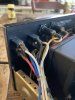
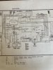
When I plug in the amp, the UV meter lights go on, whether the power button is on or not. They will not shut off unless I unplug the amp. Seems like someone overrode some part of the power switch at some point, why I have no idea. Below are some pictures I took of my unit and then the wiring diagram.
The red wire you see attached to the power switch post #5 comes from the bottom part of the switched plug.
The yellow wire you see attached to the power switch post #3 comes from the same bottom part of the switched plug.
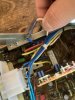
The blue and white wires that have been connected in the pic below, the blue wire comes from the top part of the switched plug, the white wire comes from the top part of the unswitched plug. This does not seem correct according to the wiring diagram.
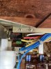
I can follow the wiring diagram but it also looks like I am missing a 4700pF disc capacitor on the power switch, but how it is wired? It's hard to see in the picture below or I don't understand it. Is one end soldered to post 3 and 4 while the other end is soldered to 5 and 6? It also looks like I am missing a 4700pF cap on the switch outlet as well.

Does anyone have pictures of this section of their NAD 3030 that they are willing to share with me so I can fix this issue? It would be greatly appreciated.

Any help is greatly appreciated, i am looking forward to fixing this unit and hearing it sing.
 

Attachments

  • IMG-4690.jpg
    IMG-4690.jpg
    120.2 KB · Views: 42
  • IMG-4694.jpg
    IMG-4694.jpg
    96.4 KB · Views: 39
  • IMG-4693.jpg
    IMG-4693.jpg
    125.3 KB · Views: 35
  • IMG-4692.jpg
    IMG-4692.jpg
    117.9 KB · Views: 32
  • IMG-4691.jpg
    IMG-4691.jpg
    123.4 KB · Views: 34
Register to hide this ad
If I understand correctly, your power ON/OFF switch has only 2 wires going to it - a red (to 'post #5') and a yellow (to 'post #3'), both of which then connect to the same bottom part of the switched outlet socket ? If that's indeed the case, then your ON/OFF switch actually does nothing, and it sounds as though someone has wired the amp to be permanently ON, whenever the amp is connected to mains power (it's quite possibly a 'bodge' because of a faulty ON/OFF switch...).

Personally, I'd remove the various cable ties (possibly also some of the excessive 'liquid tape' that seems to have been added at some point), and then trace out all of the power supply / on-off switch / switched & unswitched socket / and mains fuse wiring - so you know exactly what's connected where & what's been changed. In effect, draw your own actual schematic for the wiring, to compare to the SM info (which includes which wire colours should be where, e.g., the number codes shown in brackets). Only then can you really see what's what.

Regarding the 4700pf caps - the SM actually shows 2 for the USA version, one at the power switch, and another at the switched outlet socket - at least one of them seems to be in your photos, e.g., I suspect the RIFA cap just behind the ON/OFF switch is one of them (you should change that cap anyway - those RIFA caps age badly, and are notorious for 'letting the smoke out', quite literally (together with a somewhat noxious smell !). The green mylar cap next to the power switch could possibly be the other if someone has been in there before... ? worth at least checking anyway.

Unfortunately, there'd be no point in posting pics of my own 3030 as it's a UK version, which is wired very differently, and doesn't actually have the ancilliary switched / unswitched sockets at all.

Hope that helps a bit anyway.
 
I can follow the wiring diagram
Suggest carefully trace the wiring from the power cord, should show,
- neutral (blue?) wire connects to unswitched outlet then jumpers to switched outlet then to fuse then to voltage selector if applicable then onto transformer. Colours may differ, the wire the jumpers between un and switched is the neutral.
- power cord active (brown?) wire to other/unused position on unswitched then onto power switch position 3. Snubber cap between switch position 3 and 5 to suppress spark and prolong switch life. New wire from switch position 5 for the switched active to the unused position on the switched outlet then onto voltage selector and transformer, a class X safety cap between line and neutral on the switched outlet.
Anything else is a hack

Would be wise to unsolder wires from switch and measure resistance between positions 3&5, should be open (switch off) and near short (switch on)
 
If I understand correctly, your power ON/OFF switch has only 2 wires going to it - a red (to 'post #5') and a yellow (to 'post #3'), both of which then connect to the same bottom part of the switched outlet socket ? If that's indeed the case, then your ON/OFF switch actually does nothing, and it sounds as though someone has wired the amp to be permanently ON, whenever the amp is connected to mains power (it's quite possibly a 'bodge' because of a faulty ON/OFF switch...).

Personally, I'd remove the various cable ties (possibly also some of the excessive 'liquid tape' that seems to have been added at some point), and then trace out all of the power supply / on-off switch / switched & unswitched socket / and mains fuse wiring - so you know exactly what's connected where & what's been changed. In effect, draw your own actual schematic for the wiring, to compare to the SM info (which includes which wire colours should be where, e.g., the number codes shown in brackets). Only then can you really see what's what.

Regarding the 4700pf caps - the SM actually shows 2 for the USA version, one at the power switch, and another at the switched outlet socket - at least one of them seems to be in your photos, e.g., I suspect the RIFA cap just behind the ON/OFF switch is one of them (you should change that cap anyway - those RIFA caps age badly, and are notorious for 'letting the smoke out', quite literally (together with a somewhat noxious smell !). The green mylar cap next to the power switch could possibly be the other if someone has been in there before... ? worth at least checking anyway.

Unfortunately, there'd be no point in posting pics of my own 3030 as it's a UK version, which is wired very differently, and doesn't actually have the ancilliary switched / unswitched sockets at all.

Hope that helps a bit anyway.

Suggest carefully trace the wiring from the power cord, should show,
- neutral (blue?) wire connects to unswitched outlet then jumpers to switched outlet then to fuse then to voltage selector if applicable then onto transformer. Colours may differ, the wire the jumpers between un and switched is the neutral.
- power cord active (brown?) wire to other/unused position on unswitched then onto power switch position 3. Snubber cap between switch position 3 and 5 to suppress spark and prolong switch life. New wire from switch position 5 for the switched active to the unused position on the switched outlet then onto voltage selector and transformer, a class X safety cap between line and neutral on the switched outlet.
Anything else is a hack

Would be wise to unsolder wires from switch and measure resistance between positions 3&5, should be open (switch off) and near short (switch on)

Thank you both, I will hopefully find some time tomorrow to try and correct this as best as I can. I sounds like this has been messed with and I need to follow the wiring directions to get it back to working order. That is if the switch works.
 
That is if the switch works.
In some applications they switch both the active and neutral so switch provision is made, pin 4 & 6 are unused and might be functional.
Check resistance between pins 3&5 then check pins 4&6. You might get lucky and simply migrate wires to pins 4&6. The other option is to disassemble the switch and work out what's wrong, yeah a PITA.
 
There is a photo 'tutorial' on the forum showing a strip & rebuild of one of these early switches, including internal contact replacements - try this: http://www.audiokarma.org/forums/in...-repair-alps-push-button-power-switch.464861/ As mbz says, it's a PITA, but it's possible.
Confirmed today that it is the switch, it does not work. Next problem is the two replacement switches in the link above are either no longer available or out of stock for a while. Not sure what my next move is, it works, but not as I would like it to. Anyone in the Philly area who might have more experience and may be able to help me out?
 
Did you test pins 4 & 6? Pix are not real clear so maybe a red herring, schematic suggests pins 4&6 present and may also switch.
I did test all the pins, all pins where open when they should be closed. Wish it was that easy
 
Back
Top Bottom