pumptronics
New Member
Hello everyone at AK and thank you all for this great resource (that I often spend many hours studying).
Summary:
On this unwell 7020 I am seeing 9V DC between power supply filter cap ground and chassis earth/ground. Is this normal? This chassis is earthed to the mains lead and the wiring and earthing tab look original.
Some background:
I have a problem NAD 7020 (v2 - E2, E3 I think) which belongs to my friend. While replacing the front tuner illumination recently, he accidentally touched the soldering iron on something in that area (front left) while the unit was on. Obviously this was foolish and has done some damage somewhere that I am trying to identify. He loves his NAD units and is suitably devastated by this mistake. I am using a DBT and Variac to work on the unit.
The unit still powers on and produces distorted sound. I am guessing he shorted the transformer bulb output (blue wire) to the chassis or at least the earth of the soldering iron tip. I have tested the pre-amp section and the audio is good but the RCA outputs are carrying about 4.5V DC on them. This was enough to trigger protection on the separate power amp I used to test it. Once the protection was overcome, the sound is full and rich on both channels and all controls on the 7020 work fine. I tested the 7020 power amp section with an iPod input and the sound is tinny and distorted through headphones (and the same through speakers although switching the speakers on with a speaker attached causes quite a spike in DBT brightness and current). The sound is in both channels most of the time and always distorted. The sound sometimes pops in and out with matching DBT brightness pulses.
Not having enough skills to easily identify the exact fault (and unwilling to learn how to use my oscilloscope on this and potentially blow up everything), I began by replacing a number of components. Not the best process, I know, but it is very dirty inside and I wanted to hit it quickly, clean as I went and get it working for him. Failed there! The output transistors do NOT appear to be shorted. This unit has previously been recapped in the vertical board and main filter caps only. The vertical board regulator hot spots (ZD901, Q901, Q902 etc) were all horribly cracked so I reflowed them. Anyhow, I've since replaced/tried new regulator transistors (Q901, Q902), driver transistors (Q611, Q612, Q613, Q614), bias transistors (Q609, Q610), predriver? transistors (Q607, Q608), rectifier diodes (D901, D902, D903, D904), bridge rectifier (BD901), regulator Zener (ZD901) and now L output transistors (Q615, Q617). I am running it without the R outputs (Q612, Q614) fitted currently.
All supply voltages seem ok although perhaps the driver/output rails are a bit low at +/-25.8 (spec is 29.5V). Am seeing 29V (spec 29.5V) and -25.6 (spec -25.6V) on the rest-of-unit supply. I am also seeing 14.0 (spec 14.4V) on the Q801 supply.
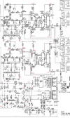
I do not have continuity between main power supply filter capacitor ground and chassis, which doesn't seem correct according to the schematic. So somehow that isn't connected and I am getting the potential difference between the two. I suspect that 9V offset is enough to make the sound totally awful, however I have no idea how this unit measured before the incident. If anyone familiar with this amp can give me an idea of normality in this department, it would be most helpful.
Next I am thinking of pulling out the (quite new) filter caps and trying some others, but I'm clutching at straws really because I don't understand how the chassis grounding can become separated from the power supply. Suggestions welcome and please ask me if you need any further info.
Thanks
Summary:
On this unwell 7020 I am seeing 9V DC between power supply filter cap ground and chassis earth/ground. Is this normal? This chassis is earthed to the mains lead and the wiring and earthing tab look original.
Some background:
I have a problem NAD 7020 (v2 - E2, E3 I think) which belongs to my friend. While replacing the front tuner illumination recently, he accidentally touched the soldering iron on something in that area (front left) while the unit was on. Obviously this was foolish and has done some damage somewhere that I am trying to identify. He loves his NAD units and is suitably devastated by this mistake. I am using a DBT and Variac to work on the unit.
The unit still powers on and produces distorted sound. I am guessing he shorted the transformer bulb output (blue wire) to the chassis or at least the earth of the soldering iron tip. I have tested the pre-amp section and the audio is good but the RCA outputs are carrying about 4.5V DC on them. This was enough to trigger protection on the separate power amp I used to test it. Once the protection was overcome, the sound is full and rich on both channels and all controls on the 7020 work fine. I tested the 7020 power amp section with an iPod input and the sound is tinny and distorted through headphones (and the same through speakers although switching the speakers on with a speaker attached causes quite a spike in DBT brightness and current). The sound is in both channels most of the time and always distorted. The sound sometimes pops in and out with matching DBT brightness pulses.
Not having enough skills to easily identify the exact fault (and unwilling to learn how to use my oscilloscope on this and potentially blow up everything), I began by replacing a number of components. Not the best process, I know, but it is very dirty inside and I wanted to hit it quickly, clean as I went and get it working for him. Failed there! The output transistors do NOT appear to be shorted. This unit has previously been recapped in the vertical board and main filter caps only. The vertical board regulator hot spots (ZD901, Q901, Q902 etc) were all horribly cracked so I reflowed them. Anyhow, I've since replaced/tried new regulator transistors (Q901, Q902), driver transistors (Q611, Q612, Q613, Q614), bias transistors (Q609, Q610), predriver? transistors (Q607, Q608), rectifier diodes (D901, D902, D903, D904), bridge rectifier (BD901), regulator Zener (ZD901) and now L output transistors (Q615, Q617). I am running it without the R outputs (Q612, Q614) fitted currently.
All supply voltages seem ok although perhaps the driver/output rails are a bit low at +/-25.8 (spec is 29.5V). Am seeing 29V (spec 29.5V) and -25.6 (spec -25.6V) on the rest-of-unit supply. I am also seeing 14.0 (spec 14.4V) on the Q801 supply.
I do not have continuity between main power supply filter capacitor ground and chassis, which doesn't seem correct according to the schematic. So somehow that isn't connected and I am getting the potential difference between the two. I suspect that 9V offset is enough to make the sound totally awful, however I have no idea how this unit measured before the incident. If anyone familiar with this amp can give me an idea of normality in this department, it would be most helpful.
Next I am thinking of pulling out the (quite new) filter caps and trying some others, but I'm clutching at straws really because I don't understand how the chassis grounding can become separated from the power supply. Suggestions welcome and please ask me if you need any further info.
Thanks