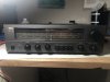
I had a NAD 7020 dropped on the bench and one of the outputs blew when I was adjusting the idle current with various fixed resistors.
So I decided to follow some of the suggestions from other folks (including @leesonic) that have repaired these units and thought I would document it here for posterity.
1. Replaced RX1/2 with 25 turn 1kOhm potentiometers
2. Replaced R643/644 with 1.2 kOhm resistors
3. Replaced blown outputs with MJ15015G/MJ15016G with new mica insulators and thermal paste
4. Cut the output transistors’ emitter traces on the PCB
5. Installed 3 Watt, 0.22 Ohm resistors on each output emitter
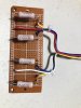
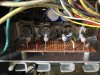
I placed the emitter resistors on a breadboard and used a couple nylon spacers from Lowe’s as standoffs and screwed it onto the heatsink using one of the existing screw holes where the u-channel fins are attached. I needed to use two longer sheet metal screws 3/4 inch long.
I tested for about an hour and the idle current and DC offsets are all stable. Yay!
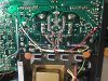
Thanks to y’all for being a good resource. Here a couple photos of the install. I used a conveniently-located existing hole in the PCB to route the emitter resistor wiring.
So I decided to follow some of the suggestions from other folks (including @leesonic) that have repaired these units and thought I would document it here for posterity.
1. Replaced RX1/2 with 25 turn 1kOhm potentiometers
2. Replaced R643/644 with 1.2 kOhm resistors
3. Replaced blown outputs with MJ15015G/MJ15016G with new mica insulators and thermal paste
4. Cut the output transistors’ emitter traces on the PCB
5. Installed 3 Watt, 0.22 Ohm resistors on each output emitter
I placed the emitter resistors on a breadboard and used a couple nylon spacers from Lowe’s as standoffs and screwed it onto the heatsink using one of the existing screw holes where the u-channel fins are attached. I needed to use two longer sheet metal screws 3/4 inch long.
I tested for about an hour and the idle current and DC offsets are all stable. Yay!
Thanks to y’all for being a good resource. Here a couple photos of the install. I used a conveniently-located existing hole in the PCB to route the emitter resistor wiring.