
• The move to the new server is done. There are some software and database maintenance updates in process. This has us passing the hat around to help out. We appreciate any donations. Seriously, even a dollar helps. The payment page may be found here - https://www.audiokarma.org/support.html

NAD 7240PE FM all static

audio rookie

New Member
Hello fellow AK'ers. Well I thought I had an easy one. Had some noise in right channel from the soft clip circuit and fixed that with replacement of some bad resistors. It had been awhile since I fully tested the unit. Aux and phono good. Connected antenna and all I get is static. I thought this worked last time I tested it, but that was 2 months ago. I am not getting any am stations either. When I did those resistors, I looked over the power board and resoldered any rough looking connections. I never touched anything on the tuner pcb. I have a schematic and will start looking that over, but thought I would get a thread started. Thanks.
 
Register to hide this ad
Hello fellow AK'ers. Well I thought I had an easy one. Had some noise in right channel from the soft clip circuit and fixed that with replacement of some bad resistors. It had been awhile since I fully tested the unit. Aux and phono good. Connected antenna and all I get is static. I thought this worked last time I tested it, but that was 2 months ago. I am not getting any am stations either. When I did those resistors, I looked over the power board and resoldered any rough looking connections. I never touched anything on the tuner pcb. I have a schematic and will start looking that over, but thought I would get a thread started. Thanks.
These units are varactor tuned. Do the procedure on Page 6 of the service manual for Tuning Voltage and see if it is within spec.
 
Thanks for the reply. I dug back into this yesterday and followed page 6 . Right from the start I realized I will have to go deeper as I had no voltage reading at the test point of R96 in both FM and AM settings. My schematic reading is very rusty and did my best to follow the circuit and find other test points for voltage. Some areas have voltage and other points I have nothing. I have no voltage at Q13 or Q14. I do have proper power at Q11 and Q12. I tried to follow some of this circuit around the board. IC801 has proper voltage, as does Q803, Q802. At Q801, emitter and base voltage is fine, but the collector which schematic says should be -24v , I am reading -25.9v. I am not sure if that is really an issue. At IC802 where schematic lists to measure -20.6v, I measure -22v. Again, not sure if that is an issue. I am getting no voltage at Q805 or Q804. I will keep digging and hope you or someone else out there has some further info. Thanks.
 
Thanks for the reply. I dug back into this yesterday and followed page 6 . Right from the start I realized I will have to go deeper as I had no voltage reading at the test point of R96 in both FM and AM settings. My schematic reading is very rusty and did my best to follow the circuit and find other test points for voltage. Some areas have voltage and other points I have nothing. I have no voltage at Q13 or Q14. I do have proper power at Q11 and Q12. I tried to follow some of this circuit around the board. IC801 has proper voltage, as does Q803, Q802. At Q801, emitter and base voltage is fine, but the collector which schematic says should be -24v , I am reading -25.9v. I am not sure if that is really an issue. At IC802 where schematic lists to measure -20.6v, I measure -22v. Again, not sure if that is an issue. I am getting no voltage at Q805 or Q804. I will keep digging and hope you or someone else out there has some further info. Thanks.
Had a feeling there was no tuning voltage.

Q804 is where you need to focus. If there's no voltage at its collector, then check to see if you have voltage at either the positive end of C821 or the cathode of D803. If there's voltage there check R809. Let us know what you find.
 
Last edited:
Q804 had .13 volts at the collector. Also measured .13 volts at positive of C821/cathode of D803. Taking a few other readings, at C810 I have .08v at positive and -.5v at negative. C826 has -27v at negative and 0v at positive. Is there any measurement I should get at D802 or D801, or am I going in the wrong direction? Not sure if this is anything, but depressing Mute for the fm, does nothing. Maybe this is still due to no voltage?
 
Q804 had .13 volts at the collector. Also measured .13 volts at positive of C821/cathode of D803. Taking a few other readings, at C810 I have .08v at positive and -.5v at negative. C826 has -27v at negative and 0v at positive. Is there any measurement I should get at D802 or D801, or am I going in the wrong direction? Not sure if this is anything, but depressing Mute for the fm, does nothing. Maybe this is still due to no voltage?
What's missing and what's needed is 41 volts at the collector of Q804. That's coming from the voltage doubler consisting of C810, D803, D804 and C821. The AC voltage should be good, because the same source feeds IC802, which is fine. You can check the AC voltage at the negative side of C801 (one lead to ground, other to C801 with meter in AC mode, should get roughly 18-20 VAC). If it's good you may have bad caps and/or diodes. Since it's an NAD I'm betting caps, especially if they're near any sources of heat.
 
Last edited:
FM and AM are all back! I replaced both C810 and C821. May have only needed C810, but did both since they were in that area of the circuit. I touched up any bad looking solder joints through out the unit as well. Thanks for your help getting to this solution.
 
FM and AM are all back! I replaced both C810 and C821. May have only needed C810, but did both since they were in that area of the circuit. I touched up any bad looking solder joints through out the unit as well. Thanks for your help getting to this solution.
Good job!

While I've pulled hundreds of good caps and replaced them, NAD's tend to use cheap caps; many of the ones I pull from one of their products are measurably bad, especially if they're near any source of heat, i.e. series pass voltage regulators or output stages.

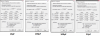
Long way of saying a recap might not be a bad idea. Check out these caps pulled from an NAD I recently worked on:

Caps.png
 
Last edited:
Wow! Just a liitle bit off I guess. LOL. I have a 7225 with no output from the preamp. I have 2 caps in there that had some powdery residue on top, and plan to recap all of the preamp. The amp section tested good. What kind of tester are you using to measure caps? I realized my VM doesn't go high enough and was thinking of getting a fluke 117.
 
Wow! Just a liitle bit off I guess. LOL. I have a 7225 with no output from the preamp. I have 2 caps in there that had some powdery residue on top, and plan to recap all of the preamp. The amp section tested good. What kind of tester are you using to measure caps? I realized my VM doesn't go high enough and was thinking of getting a fluke 117.
Test results I posted are from a Dayton DATS computer based system. I also have a Peak Atlas ESR70.
 
Wow! Just a liitle bit off I guess. LOL. I have a 7225 with no output from the preamp. I have 2 caps in there that had some powdery residue on top, and plan to recap all of the preamp. The amp section tested good. What kind of tester are you using to measure caps? I realized my VM doesn't go high enough and was thinking of getting a fluke 117.
Before you recap that 7225 fix it first. I'd check the +/- 28V power supplies.
 
Back
Top Bottom