• The move to the new server is done. There are some software and database maintenance updates in process. This has us passing the hat around to help out. We appreciate any donations. Seriously, even a dollar helps. The payment page may be found here - https://www.audiokarma.org/support.html

NAD C162 preamp fix

JustDabbling

New Member
Hi all, looking for help in trying to get a NAD C162 (circa 1999 - board N6C1162DD01 DC741130) up and running.


About me, setup and goals:

I’m using this project to learn more about analog electronics and would love that it could be fixed but not too worried if it can’t.

I took some EE courses years ago in uni but nothing really hands-on except those labs.

I have a fluke 115 that’s probably 20yrs old and recently picked up this fnirsi so-510 oscilloscope (couldn’t resist for $50). Also, have a basic de/soldering setup. I’m not interested in upgrading / getting more gear and not worried if things take longer b/c I can only trust the multimeter, this is a side project that I’ll play around with when I have time and the urge.


The story so far:

Was playing some music reasonably loud went outside and came back in to the smell of something burning. Switched everything off, unplugged it all.

Cracked the preamp open and saw that 2 fuses were fried (F706 and F707 both 250v 0.5A pre rectifier).

Started poking around with the multimeter and found Q701 (2SB647A transistor looked to be toast), pulled it and saw it was cracked and a little melted, also read 4ohms across some of the pins (can’t remember which), so decided it needed to be replaced.

Dug around and found a replacement part on amazon and when it arrived the diode testing mode at least showed it looked like a transistor.

Popped it in, changed the fuses out, used fast-fail ones just in case, and lo and behold, both fuses popped again and so did the transistor I just put in.


Round 2:

More multimeter probing and further downstream I found voltage regulator IC701 (LM317) measuring differently than IC702 (LM337) pulled both out and not sure whether they are good but blindly measuring resistance across every pin and every polarity I see a max of 41 Mohm in the 317 and 8 Mohm in the 337, no idea what that means but since they are mirrors of each other I would have not have expected this difference.


Round 3:

Started looking further downstream thinking that some short exists further in the circuit. Since it’s the 52V source that’s at issue and it feeds something called MD1B module thought to dig into it.

Found a scorched 100V 0.1uF cap (C807) looks like it straddles -52V and ground(?). The reciprocal cap (C806) between +52V and ground looks ok.

Resistance is 88ohm on the bad cap but i’m wondering is this just another victim or the culprit?

The other channels’ identical MD1B module doesn’t have any burn marks and the cap shows resistance as it charges up so I’m guessing the module may be ok.

Jumping back to the bad module, I did diode tests on each of the 2 big heat-sinked transistors SD669A (Q807) and SB649A (Q808) thinking they might have contributed to the fried cap but they seemed ok at least compared to the other modules ones.

Still I’m wondering if there is some other part(s) on this module that may have caused the issue. Or even if it could be further downstream but I doubt it since these are the only parts of the circuit that are drawing off the 52V lines.


Questions

  1. does it seems plausible that this tiny capacitor is responsible for the issue? If so why and is there some other part that caused it to fry?
  2. In replacing the burnt cap should I go for a higher voltage one?
  3. Seems many people talk about re-cap’ing the board for all electrolytic caps - folklore or fact?
  4. In searching Nichicon I see no less than 50 product lines of electrolytic caps, how does one even begin to decide which line to choose from? Any general rules of thumb / advice for audio equipment?
  5. Transistor Q701 needs replacing (see above) and I’m thinking to replace both it and its sister Q702, which are paired; 2SB647A and 2SD667A. These parts are obsolete so how to go about finding replacements that have the characteristics?
  6. Can I test the voltage regulators LM317 and LM337 given the gear I have? What would be the minimum equipment needed?
Thanks so much for bearing with me and in advance for any / all advice.

Apologies if some of these topics are already covered elsewhere if you could link, so I can learn, I would be most grateful.

Cheers,

Rick
 
Register to hide this ad
Round 4

Correction transistor Q702 was bad, replaced it (2SD667A) with a KSC2383YTA.

Pulled both channels’ MD1B modules. Replaced the voltage regulators and am now seeing +53v and -59v.

The schematic calls for +-52v. But since there is no draw (only the MD1B modules tie to the 52v sources) I’m wondering if this is ok?

Or should I switch out the resistors to get the regulators closer to +-52v or does it not matter much?
 
You might get some helpful replies if you can post a circuit diagram.
The output of a regulator showing 59V instead of 52V seems suspicious. I'd expect the output from an LM337 to be closer to spec than that.
 
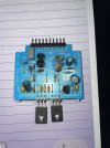
Could you also post a clear overhead photo of the internals of one of the MD1B modules ? It's not immediately obvious to me which components are (or are not) installed within the MD1B's. I wouldn't refit them until you've been able to confirm all the PS voltages are good, and checked the modules themselves.

Otherwise, I'd also be checking D703, D704 in the power supply area, and probably checking & changing all the 50V rated electrolytics in that particular section of the power supply, if they are indeed 50V rated. I find it hard to believe that NAD would have made that basic a mistake in reality, but the following link does suggest they did...

52V PS Failure NAD C160....
 
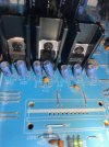
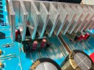
Thanks Goldie99. C716/7 and C742/56 are indeed 50v (photo attached). None seem shorted; I checked resistance in-circuit and they settled around 5kohm, not sure how valid that is.

Also checked the diodes D704 which measured (again in-circuit) a 0.53v drop in one direction and 0.86v in the other. D703 showed 0.53v and 0.78v again in circuit with the diode tester.

I compared this against the diodes on the 26v side D707/8 and they measured similarly. Most other diodes in the circuit measured inf one way and 0.5v the other, which I kinda expected for all of them. So not really sure how to interpret these results.

I also checked the resistors mentioned in the post and they all measured to spec. But yes I’m not going to put the modules back until the pose side is completely sorted.

The module photo below is the one w/o burnt C807. The other pic shows the 50v caps mentioned above.
 

Attachments

  • IMG_2800.jpeg
    IMG_2800.jpeg
    105.6 KB · Views: 21
  • IMG_2798.jpeg
    IMG_2798.jpeg
    138.3 KB · Views: 21
I'd change C716/717 & C742/756 anyway, I just find 50V rated caps on 52V rails somewhat 'marginal'. It may not be the issue now, but it's a problem waiting to happen in my opinion.

Am I understanding your voltage numbers correctly ? so you have both the +/- 59V present, but after the regulators you have +52V and -59V ? If so, for the 2 mins work, I'd change D704 anyway and check again (your tester only applies a low voltage so may not be a reliable test).
 
Will update the capacitors you mentioned goldie99 once parts arrive.

In the meantime I had another look at the regulators and realized I only swapped out IC701 (lm317). After replacing IC702 (lm337), voltages are slightly better 53.09 and -54.8.

I wanted to understand better why the deviation from spec so I used spice to simulate and found according to the schematic I should be seeing 50.7 / -52.0.

Went ahead and measured the voltage dividers used to adjust the regulators and found both to be slightly out of spec at 115 / 4775 ohms and 115 / 4950 ohms. Using these values the simulation gave 51.5 / -54.7

Also calculated the outputs using the onsemi data sheets for the devices and got 53.15 / -55.05 which is pretty much exactly what was measured.

So it looks like getting the voltage dividers closer to spec resistances should help but I’m wondering how close to 52v do they need to be?

All the other voltage rails (26, 18, 12 and 5) are almost bang on their voltages so I assume the 52v needs to be dialed in as close as possible.
 
Was about to order parts and did another pass on measuring the module components and found R807 was open on M302; the module where C807 was burnt. Now I’m wondering what other parts could be dead on this board?

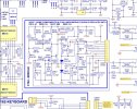
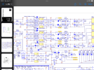
Attached the schematic and looking for ideas of failure modes and how to ensure all parts are ok in this module?

In summary, the negative voltage regulator failed (feeding pin 10 in the circuit) and C807 smoked.
 

Attachments

  • IMG_0097.jpeg
    IMG_0097.jpeg
    175 KB · Views: 12
The output voltages from the LM317/337 are determined by the values of the R705-708 resistors, so with two of them clearly out of spec. it's hardly surprising the voltage rails are wrong (they should be 1% tolerance metal films). Are the resistor colour codes correct ? or has someone simply put the wrong parts in ?

In any case, the +/-52V supplies have clearly taken a 'hit'. Ideally, they'd need rebulding with new e-caps, new diodes, and new MF resistors, as well as just the regulators, it costs so little it's not worth skimping on it.

In terms of tracking your original fault(s), I think you're going to need to dig much deeper into the MD1B module. You simply can't access it in situ within the amp, so unless you have the facilities to power it up separately on the bench, with current limiting, then you're probably limited to checking it part by part... I doubt either C807 or R807 was 'the' issue as such, they are more likely just casualties.

If you haven't got the facility to power it on the bench, then I'd suggest to first check the 3X e-caps, heat in a closed 'box' module could be an issue... if you're lucky, one of the e-caps might have shorted and not taken out half the Silicon. Then maybe drop the 7x transistors off the board and test them separately, and then measure the rest of the components in situ, while the transistors are out of the way.... take your pick...

That's my 2¢ anyway.
 
Thanks for the guidance, ordered a bunch of parts and will rebuild the 52v rails when they arrive.

As for the module, I don’t have the gear to test it so I’ll take your advice and start the tear down in a week or two when I next get to it.
 
Finally got some time to work on this again and looks like I made things worse...

I swapped some of the bad parts and all the rail voltages looked solid, got excited and assembled it all back up (modules in) and gave it a test run. Sadly it didn't do anything. Unplugged it and chucked it in a corner until just now.

Unfortunately, all the power rails except the 5V one look to be toast.

Upstream of the regulators I'm seeing voltages of +/-75V R701/R702, +/-45V R709/R710 and 22V R717. I'm seeing a small drop (~0.5V) on the other side of each of the resistors that connect to the base of each of the transistors.

Sadly, on the collector side of the transistors everything is 0V.

I've measured C712/713/724/725/733 relative to ground on both sides and they are showing zero. I can't even tell if the DBT bulb is lighting up, its so dim, so I don't believe there are any shorts. I don't see scorch marks and I didn't smell anything so I'm at a loss to explain what happened.

Now that I have some parts I'm thinking about rebuilding everything downstream of the big caps..i.e. the advice from Goldie99 that I should have followed in the first place.

My concern is that once this is all done whatever is/was the culprit(?) will just fry all the parts again. I've pulled the MD1B modules and now have a bench power supply so I can check those boards independently, but now that the 26V and 12V rails are toast I'm worried that there could be more damage beyond just the 2 x MD1B modules.

Looking for suggestions on how to proceed once I've re-built all the supplies.

Thanks!
 
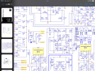
Can anyone tell me how the circuit producing VCTM/P interacts with the power rails? I see see it feeds to the base of the transistors across a voltage divider but what does it do?

Attached two schematics…
 

Attachments

  • IMG_0099.png
    IMG_0099.png
    283.4 KB · Views: 7
  • IMG_0098.png
    IMG_0098.png
    294.3 KB · Views: 7
Hi all, looking for help in trying to get a NAD C162 (circa 1999 - board N6C1162DD01 DC741130) up and running.


About me, setup and goals:

I’m using this project to learn more about analog electronics and would love that it could be fixed but not too worried if it can’t.

I took some EE courses years ago in uni but nothing really hands-on except those labs.

I have a fluke 115 that’s probably 20yrs old and recently picked up this fnirsi so-510 oscilloscope (couldn’t resist for $50). Also, have a basic de/soldering setup. I’m not interested in upgrading / getting more gear and not worried if things take longer b/c I can only trust the multimeter, this is a side project that I’ll play around with when I have time and the urge.


The story so far:

Was playing some music reasonably loud went outside and came back in to the smell of something burning. Switched everything off, unplugged it all.

Cracked the preamp open and saw that 2 fuses were fried (F706 and F707 both 250v 0.5A pre rectifier).

Started poking around with the multimeter and found Q701 (2SB647A transistor looked to be toast), pulled it and saw it was cracked and a little melted, also read 4ohms across some of the pins (can’t remember which), so decided it needed to be replaced.

Dug around and found a replacement part on amazon and when it arrived the diode testing mode at least showed it looked like a transistor.

Popped it in, changed the fuses out, used fast-fail ones just in case, and lo and behold, both fuses popped again and so did the transistor I just put in.


Round 2:

More multimeter probing and further downstream I found voltage regulator IC701 (LM317) measuring differently than IC702 (LM337) pulled both out and not sure whether they are good but blindly measuring resistance across every pin and every polarity I see a max of 41 Mohm in the 317 and 8 Mohm in the 337, no idea what that means but since they are mirrors of each other I would have not have expected this difference.


Round 3:

Started looking further downstream thinking that some short exists further in the circuit. Since it’s the 52V source that’s at issue and it feeds something called MD1B module thought to dig into it.

Found a scorched 100V 0.1uF cap (C807) looks like it straddles -52V and ground(?). The reciprocal cap (C806) between +52V and ground looks ok.

Resistance is 88ohm on the bad cap but i’m wondering is this just another victim or the culprit?

The other channels’ identical MD1B module doesn’t have any burn marks and the cap shows resistance as it charges up so I’m guessing the module may be ok.

Jumping back to the bad module, I did diode tests on each of the 2 big heat-sinked transistors SD669A (Q807) and SB649A (Q808) thinking they might have contributed to the fried cap but they seemed ok at least compared to the other modules ones.

Still I’m wondering if there is some other part(s) on this module that may have caused the issue. Or even if it could be further downstream but I doubt it since these are the only parts of the circuit that are drawing off the 52V lines.


Questions

  1. does it seems plausible that this tiny capacitor is responsible for the issue? If so why and is there some other part that caused it to fry?
  2. In replacing the burnt cap should I go for a higher voltage one?
  3. Seems many people talk about re-cap’ing the board for all electrolytic caps - folklore or fact?
  4. In searching Nichicon I see no less than 50 product lines of electrolytic caps, how does one even begin to decide which line to choose from? Any general rules of thumb / advice for audio equipment?
  5. Transistor Q701 needs replacing (see above) and I’m thinking to replace both it and its sister Q702, which are paired; 2SB647A and 2SD667A. These parts are obsolete so how to go about finding replacements that have the characteristics?
  6. Can I test the voltage regulators LM317 and LM337 given the gear I have? What would be the minimum equipment needed?
Thanks so much for bearing with me and in advance for any / all advice.

Apologies if some of these topics are already covered elsewhere if you could link, so I can learn, I would be most grateful.

Cheers,

Rick
Hi, are you still working on this pre-amp? I am working on same preamp and can share experiences if that helps.
 
You need to get the power supplies up an running again.

the power supply works like this....

When you switch power ON (assuming no blown fuses) the IC706 5v regulator should produce +5.5V at it's output, ie across C740.

The +5.5V powers the IC502 which then drives the front display lights (do you see any lights?) and also powers up Pin 18 "P ON/OFF".

P ON/OFF then goes to the transistors Q714 and Q713 which switch state. Q714 and Q713 drive via VCTP and VCTM transistors Q701 and Q702 respectively, and also Q703&Q705 and Q704 which all switch ON to provide power to the voltage regulators IC701, IC702, IC703, IC704 and IC705.

Now the IC701, IC702, IC703, IC704 and IC705 circuitry is bad design because they generate more heat than the small heatsinks can dissipate without getting very hot. Also resistors R705, R706, R707 and R708 are dissipating too much heat as they are overdriven and will look burnt. Replace these 4 resistors with 1 WATT resistors of same value.

I have seen a few pictures of the Pre-amp PCB in this IC701, IC702, IC703, IC704 and IC705 area being brown from excess heat. In my preamp I attached a big heatsink to all the small heatsinks (using silicon insulators since the small heatsinks are live). You don't have to do this extra heatsink to be operational - the regulators will just very hot.

Note have also replaced all the electroytic capacitors (105oC rated) and polyester capacitors(with MKT). Taking note of the operating voltages.

Good luck.

IMG_3496.JPGIMG_3539.JPGIMG_3541.JPG
 
Back
Top Bottom