Alonia
Member
After a long time where I was no longer active here I would like to throw an interesting project into the room and maybe someone can help me.
Normally I mainly deal with Yamaha devices but for once a NAD Model 300 has found its way onto my desk.

There was a note on the lid (transistors replaced but no signal) so there has already been a repair attempt that failed... great
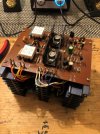
Left channel looks untouched and in the right one you could see changed components at first glance so I took a close look at what has already been done and what else is broken.
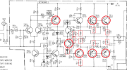
I have marked here what has already been replaced and which defective components I have still found.
The 4 exchanged Toshiba transistors didn't look very original. That's why I decided to exchange all already exchanged components again except for the TR609 transistor (Safety first ).
).
In the end, a transistor fails because it says 2SC2240, for example, but does not comply with the data in the datasheet...
I have selected the following components as replacement types:
TR604 -> 2SA914 --> KSA1381
TR605 -> 2SC1953 --> KSC 3503
TR606 -> 2SC945 --> KSC2383
TR607 -> 2SA733 --> KSA1013
TR609 -> 2SA762 (The installed transistor looks original, but has been replaced because the letters of the rank? are different [HJ-22 instead of JA-22]).
I have decided to take over the transistor due to the case. In the untouched channel they are both the same rank?, i.e. both are labeled with JA-22.
If i need to replace TR608 and TR609 later i need to make some modifications due to the case:
TR608 -> 2SC1431 --> MJE15028/30 (TO-220)
TR609 -> 2SA762 --> MJE15029/31 (TO-220)
TR610 / TR611 -> 2SD427 --> MJ21196G
TR612 / TR613 -> 2SB557 --> MJ21195G
D604 -> 1S2473 --> 1N4148
Now we come to the actual problem:
The first time I switched it on with a current limiter (DBT), I noticed that I had a rising positive voltage at the output of the repaired channel. (+25V)
So I checked the 4 emitter resistors again (although I replaced all 4). So far ok.
Then I checked all diodes again and couldn't find anything.
Regarding the KSC2383 and the KSA1013 I know that they have a much lower fT but that would not explain the error (in my opinion).
Unfortunately I have no MJE15028/30 and MJE15029/31 in my collection of components to rule out that the transistor TR609 is my problem.
I'll check everything again today to see if I've overlooked anything or messed up a transistor, which I don't think because I always check everything 3 times.
The untouched channel does not have this problem and works perfectly.
I wouldn't say that I can't solve this problem, but I thought I'd share this project.
Maybe someone will need it later.
Update:
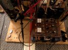
The error was caused by the TR609 transistor. If this thing is a fake, then it's a really good one. I used a pair of Sanken 2SA1859A / 2SC4883A for testing. These have a 3W lower collector dissipation but for testing with a DBT it gave me the result I wanted. What does that tell me... You should remove and change everything that you have not installed yourself. Unless you want to test the parts with a curve tracer.
I will also replace TR606 and TR607 with another pair that has better values.
So, don't buy transistors in the bay or anywhere else, because in the end you could have repaired your amplifier, but it won't work because of stupid errors like the one.
It's better to choose a suitable replacement from Mouser or Digikey if possible.
Cheers
Alonia
Normally I mainly deal with Yamaha devices but for once a NAD Model 300 has found its way onto my desk.
There was a note on the lid (transistors replaced but no signal) so there has already been a repair attempt that failed... great
Left channel looks untouched and in the right one you could see changed components at first glance so I took a close look at what has already been done and what else is broken.
I have marked here what has already been replaced and which defective components I have still found.
The 4 exchanged Toshiba transistors didn't look very original. That's why I decided to exchange all already exchanged components again except for the TR609 transistor (Safety first
).In the end, a transistor fails because it says 2SC2240, for example, but does not comply with the data in the datasheet...
I have selected the following components as replacement types:
TR604 -> 2SA914 --> KSA1381
TR605 -> 2SC1953 --> KSC 3503
TR606 -> 2SC945 --> KSC2383
TR607 -> 2SA733 --> KSA1013
TR609 -> 2SA762 (The installed transistor looks original, but has been replaced because the letters of the rank? are different [HJ-22 instead of JA-22]).
I have decided to take over the transistor due to the case. In the untouched channel they are both the same rank?, i.e. both are labeled with JA-22.
If i need to replace TR608 and TR609 later i need to make some modifications due to the case:
TR608 -> 2SC1431 --> MJE15028/30 (TO-220)
TR609 -> 2SA762 --> MJE15029/31 (TO-220)
TR610 / TR611 -> 2SD427 --> MJ21196G
TR612 / TR613 -> 2SB557 --> MJ21195G
D604 -> 1S2473 --> 1N4148
Now we come to the actual problem:
The first time I switched it on with a current limiter (DBT), I noticed that I had a rising positive voltage at the output of the repaired channel. (+25V)
So I checked the 4 emitter resistors again (although I replaced all 4). So far ok.
Then I checked all diodes again and couldn't find anything.
Regarding the KSC2383 and the KSA1013 I know that they have a much lower fT but that would not explain the error (in my opinion).
Unfortunately I have no MJE15028/30 and MJE15029/31 in my collection of components to rule out that the transistor TR609 is my problem.
I'll check everything again today to see if I've overlooked anything or messed up a transistor, which I don't think because I always check everything 3 times.
The untouched channel does not have this problem and works perfectly.
I wouldn't say that I can't solve this problem, but I thought I'd share this project.
Maybe someone will need it later.
Update:
The error was caused by the TR609 transistor. If this thing is a fake, then it's a really good one. I used a pair of Sanken 2SA1859A / 2SC4883A for testing. These have a 3W lower collector dissipation but for testing with a DBT it gave me the result I wanted. What does that tell me... You should remove and change everything that you have not installed yourself. Unless you want to test the parts with a curve tracer.
I will also replace TR606 and TR607 with another pair that has better values.
So, don't buy transistors in the bay or anywhere else, because in the end you could have repaired your amplifier, but it won't work because of stupid errors like the one.
It's better to choose a suitable replacement from Mouser or Digikey if possible.
Cheers
Alonia
Last edited: