• Please note that Audiokarma will be offline briefly for updates early on Monday morning, September 28th.

Nakamichi Receiver 1, locked=orange led

Erika_DV

New Member
I bought my Nakamichi Receiver 1 in 1992 and have a pair of KEF Calinda's for speakers.
Over the years the tuning indication became 'weaker' and the last year it would only lock in stereo when tuned to the FM frequency + 0.2 Mhz. Last month it would not lock stereo any more.
Having read a few post here I was tempted to upgrade some of the caps.
I have been fiddling with tube amps for the last 20 years.

Before I started I took some voltage readings: 12V=11,8V, 30V=28,4V. (Fluke 867)
I replaced the original filter caps ELNA 10.000µF 63V 85°C with EPCOS 10.000F 63V 85° 6.3A
https://be.farnell.com/epcos/b41231...-alu-elec-snap/dp/2284051?CMP=i-bf9f-00001000
-Vcc= -55,6V, +Vcc= +55,3V Manual states: -53,8V / +53,6V. Other voltages still 11.8V & 28.4V :(
Tested the Receiver 1 everything was working fine but still the locking problem.
Next I replaced the 7812 and cap C406 with a new L7812ABV and 1000µF 25V.
Tested the Receiver 1 everything was working fine. 12V=12.1V
I found that the 30V is controlled by two series zener diodes of 15V according to the service manual
Reading on-board: 14.3V D404 and 14.1V D405. They have to be replaced.
So far so good.
Because it was going well I decided to replace caps C411 & C412 100µF 35V as they are part of the 30V regulation. Being careful with the polarity I replaced the both.
Tested: Orange LED ! Oh no....
I put the original caps back, which tested 102µF and 110µF, it had no effect.
Question: how do I get my Receiver 1 operating again?
Any suggestions will be welcome.

Thanks,
Erika
 
Last edited:
Register to hide this ad
I bought my Nakamichi Receiver 1 in 1992 and have a pair of KEF Calinda's for speakers.
Over the years the tuning indication became 'weaker' and the last year it would only lock in stereo when tuned to the FM frequency + 0.2 Mhz. Last month it would not lock stereo any more.
Having read a few post here I was tempted to upgrade some of the caps.
I have been fiddling with tube amps for the last 20 years.

Before I started I took some voltage readings: 12V=11,8V, 30V=28,4V. (Fluke 867)
I replaced the original filter caps ELNA 10.000µF 63V 85°C with EPCOS 10.000F 63V 85° 6.3A
https://be.farnell.com/epcos/b41231...-alu-elec-snap/dp/2284051?CMP=i-bf9f-00001000
-Vcc= -55,6V, +Vcc= +55,3V Manual states: -53,8V / +53,6V. Other voltages still 11.8V & 28.4V :(
Tested the Receiver 1 everything was working fine but still the locking problem.
Next I replaced the 7812 and cap C406 with a new L7812ABV and 1000µF 25V.
Tested the Receiver 1 everything was working fine. 12V=12.1V
I found that the 30V is controlled by two series zener diodes of 15V according to the service manual
Reading on-board: 14.3V D404 and 14.1V D405. They have to be replaced.
So far so good.
Because it was going well I decided to replace caps C411 & C412 100µF 35V as they are part of the 30V regulation. Being careful with the polarity I replaced the both.
Tested: Orange LED ! Oh no....
I put the original caps back, which tested 102µF and 110µF, it had no effect.
Question: how do I get my Receiver 1 operating again?
Any suggestions will be welcome.

Thanks,
Erika
Hello Erika! Welcome to AK. Well it is hard to say what "went wrong" not being able to see it through your eyes. It is very possible there is a bad trace from soldering, or a funky solder joint, or even a solder bridge. Also, check for any other "bad" or cracked solder joints that happen with age, and thermal cycling. Even ones you never touched. Many older units suffer the same fate no matter what brand. I personally always take lots of detailed photos before warming up the soldering equipment. That way I have a visual reference and can check everything like component orientation, or wiring, etc. to check my work. It is also possible a resistor or other component is bad, or going bad too, which may have led to the regulator failure to begin with, and just resurfaced.
 
Fond it!
The controller is locked-up.
I searched the manual and found pin 39 as RESET for the µP U001.
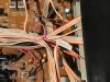
To get to the RESET point on the display PCB I had to take the whole front off. I did not have to disconnect the wires as I could just reach the RESET point to solder a (pink)wire to it.
Then I switched the amp on - Orange led. As soon as I touched the Reset Wire to the chassis the amp came alive!! All functions working.
Back to the power supply : Caps C411 & C412 were replaced.
Power on : Orange Led + RESET = amp working. Tested voltage on CN-4 on main board: 28.4V-0V-12.0V
No change to the situation...
Next : replace ZD404 and ZD405.
Bought 4 15V 0.5W Zener diodes in the local store.
YouTube told me how to measure the value of a Zener with a power supply, 1K resistor and a multimeter.
Values: 15.4V, 15.2V, 15.1V and 15V. Used 15.1V and 15V.
Replaced the Zeners + checked the soldering and connections.
Power on amp : Orange led...again. Used Reset wire and the amp booted. YES!
Voltage supply on main board CN-4 30V-0V-12.1V = perfect.
Now the FM tuning has changed: the Auto search locks into the the station at the correct frequency but the Stereo lock does not come on.
If I manually change the frequency up by 0.05Mhz the stereo locks and I have good separation. It would do that before I started but I had to change up 0.2 Mhz.
The search goes on.....

I will update soon...

Some pics of the Reset Wire:
 

Attachments

  • IMG_6691.jpg
    IMG_6691.jpg
    104.2 KB · Views: 13
  • IMG_6696.jpg
    IMG_6696.jpg
    137.1 KB · Views: 13
Last edited:
Next up the main board.
I thought it would be a good idea to replace all the parts that had ‘burned’ the PCB.
Especially the Zener diodes and resistors of the Local Power Supply.
Zener diode 18V 500mW
ZD306 & ZD307
Resistors 250mW
R351, R352, R353, R354 2K2
R355, R356 680
R357, R358 2k2
Because the resistors are bigger than the original I put them in straight up.
I fitted clip-on heat sinks, with some modification to Q317, Q318, Q321 and Q322.
Caps C313R and C314R 220µf 63V looked like they leaked so I replaced them.

Because I thought that caps were the cause of the diverting stereo locking I replaced
Round U004
C166 0.022µf 50V Z
C167 47µF 16V
Round U003
C159 0.22µF 50V Z
C160 1µF 50V (was electrolyte replace with ceramic)

After all this work it was time to test Receiver 1: Power on = all systems go!
I checked the different voltages as they were noted on the schematic and compared them to what I found on the amp.
The only difference I could find was in the Local Power Supply Q317 base was 19V but Q320 was -18.8V where it should be -19V
Sound was better than before and I got the impression that the stereo separation was better.
I let the amp run in this state for a few hours.
No problems everything fine except for the Stereo locking. Still the same problem.
At this point I gave up looking for the locking problem and decided I would follow the calibration list in the service manual to see if it would improve the sound or tuning.
First up Idling Current.
Connected the DMM to TP5 & TP6, CD selected, Volume min., speakers off, shorted the CD input jacks with short audio cinch cable. Use plastic screwdriver to adjust VR301R. Was -23mV set it very carefully to 4mV. This took some trail and error because the system would react to the adjustment but in the end I got it on 4mV.
Next TP3 & TP4 and VR301L Initial measurement 80mV. Again I turned the VR301L carefully… it jumped to -200mV. I was surprised by the jump and in a reaction I turned it back.
Then BANG - FLASH at the back of the amp near the speaker relay and a flash from the bottom of the amp.
I looked up and saw the fuse 2.5A 250V (left fuse) was gone.
*S**T*
Checked the bottom: tested the Power transistors with DMM in diode setting : Channel near the back (Right channel?)all OK but Channel near the front (Left channel): 2SA1492Y and 2SC3856Y - shorted both sides, 2SA957 half shorted.
What a shock - I did not expect that.
I was so disappointed in myself that I just closed the amp and put it on the shelf.
I just can’t think of all the parts that were damaged in the blow-out.
Internet search gave me a page of someone in Germany that made exactly the same mistake. He replaced the defective MOSFETs and the speaker relays.
http://www.hifi-forum.de/viewthread-185-16084.html (it’s in German).
Made me feel a little better - I am not the only one to make the stupid mistake.

Any suggestions on how to go about solving this - were do I have to look for defective parts?
Erika
Still mad at myself….:-(
 
Back
Top Bottom