• The move to the new server is done. There are some software and database maintenance updates in process. This has us passing the hat around to help out. We appreciate any donations. Seriously, even a dollar helps. The payment page may be found here - https://www.audiokarma.org/support.html

Nakamichi TA 2A, High DC offset

EC1

Super Member
I just measured DC offset on my Nakamichi TA 2A today and found the right channel to be around 110 mv, and the left is pretty good at around 2.0 mV. I have set the bias according to the service manual. There seems no adjustment for DC offset.
The thing I learned here is I might be able to improve the right channel DC by changing out the differential transistors pair with a new machining pair. By looking at the schematic, I am guessing the pair is Q301L/Q302L, Q301R/Q302R respectively.
Can someone kindly confirm this for me? And the substitute from what I read here again, the KSC1845 could be a good one? or something else?
Thanks a lot.
Screenshot 2021-06-06 162332.png Screenshot 2021-06-06 162453.png
 
Register to hide this ad
Those are the differential pairs. I've also seen KSC1845 as a recommended replacement for 2SC2240, but I have no knowledge that it is either an ideal replacement in this particular circuit, or if better replacements exist.

You are probably aware that the transistors in each pair need to be closely matched for hfe, and that this usually involves getting many more than you need and then sorting through them to make the closest-matching pairs you can.
 
@northpaw, thanks for your response. Neither do I can tell where the KSC1845 is the good replacement in my case and seeking help here.
Yes, I am aware of the matching requirement here. Will see what I can do from what I have in hand once I KSC1845 is confirmed.
Anyone else?
Thanks.
 
So I removed Q302R and Q301R, after some disconnected wire connectors and lifted the tuner board, I think. The hfe measured as 379 (Q302R) and 550 (Q301R), not sure this difference causing the high DC offset at the right channel? Go ahead replace them with a pair of KSC1845FTA with matching hfe at around 382. Did not touch the ones at the left channel though.
Solder them on. Put back all the wire connectors. Power on, no smoke.
But measure the DC at the right channel, still at 77.0. dropped from the original 110. some improvement but disappointed.
Should I try KSA992? or should I try something else?
Hook back up to the system, it sounds as good as earlier, cant hear any difference. One surprise is that this seems cure the volume unbalance between L and R, used to be weaker at the right channel and the balance knob needs to be around 1, 1:30 position. Interesting to me.
InkedIMG_6894[1589]_LI.jpgInkedIMG_6895[1591]_LI.jpg
 
The thing I learned here is I might be able to improve the right channel DC by changing out the differential transistors pair with a new machining pair.

The hfe measured as 379 (Q302R) and 550 (Q301R), not sure this difference causing the high DC offset at the right channel?
But measure the DC at the right channel, still at 77.0. dropped from the original 110. some improvement but disappointed.
The DC offset would be zero if Q302R and Q301R were perfectly matched at the collector current used in the amp and if the DC resistance from both bases to ground were the same.
Usually there are two resistors which determine the resistance from base to ground, but this amp is a bit more complicated. Anyway, one simple thing you could try is changing capacitor C306. Any leakage across it would upset the DC offset.
 
It will be interesting to see if replacing C306 helps. Note that C306 is marked as (LN), which is low noise, or low leakage and low ESR. Seems Nakamichi thought the cap at this location was important to sound quality. A suitable quality electrolytic should be used here.

On the improvement of channel balance, perhaps the high DC offset on the right was "pre-tensioning" the cone, resulting in some attenuation of its output; just a guess.
 
@rothwellaudio, thanks for the hint, will look into this. First got to see whether I have the part on hand or not.
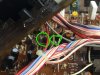
I also notice some scorched area on the main PCB, not a good pic attached, will take better pic later. Want to address the DC issue first and did not really look into that yet.
InkedIMG_6897[1595]_LI.jpg

@northpaw , did found some of your old post, will probabbly need to address those too.
^^ what glen says.

There are a few known issues with this receiver that you should check as well, some of which could relate to your issue:
-- the original resistors R309L and R309R on the main PCB were a bit under rated and can fail. They are 22KΩ, half watt; replace with metal oxide resistors, 1W or better
-- Q525 on the logic board was also under rated and can fail (see addendum in the SM). I used a PN2907A-AP (suggestion of Mannegizen) but note you have to fold the leads to get the right ECB pin order
-- check solders of the speaker relay on the PCB. Its been common experience reported here that they develop a poor connection to the PCB, and can be remedied by reflowing (see posts by Freddymac).
-- check around Q207 and Q208 (main board, for bad solders as well, as they run hot. They are in the +/-18V regulator circuit, and you can check those voltages at CN-24, Pins 1 and 2 (Pin 3 is ground).
-- once you get it running, be sure to check the amp bias, and set to factory specs.

Welcome to AK, BTW.

If you search here, and at diyaudio, you will find a number of threads on TA-2s, and they contain a lot of good info. Most of the little I know about fixing the Nakamichi receivers I learned from member Mannegizen, and hopefully he will show up soon. They are great sounding units, definitely worth fixing.

Also, if you don't already have a copy of the SM, you can download it from hifiengine (need to register, but its free, and safe).
 
I took a look, and I don't see a currently available device with matching specs to PN2907A-AP. There may be ones that are even superior, but judging what is critical or merely just adequate isn't a skill I have. I do know that the replacements for the original device Nakamichi used (which was a garden-variety transistor) were selected for greater power dissipation (the PN2907A-AP was 600mW, vs less than 250mW for 2SA733). I suspect there is an adequate device out there.

I did see a KSA1381ESTU at Digikey that is probably superior in most (if not all) respects and is in stock and can be bought in quantities as low as 1, and isn't expensive. Where it seems it might be deficient to PN2907A-AP is in Vce(sat), but the tabulated spec is given under different conditions for each and I don't know how to read the curves (when supplied) in order to compare. But the Vce(sat) for KSA1381ESTU (600mV at Ic=20mA, Ib=2mA) seems to exceed the spec for the original 2SA733, but again, the values are for different conditions. Someone with more experience than I would have to evaluate. The KSA1381ESTU does have excellent power handling: 7W, far in excess of what is needed here.

If you can't find what you need, I'm sure I have a spare or two of the PN2907A-AP somewhere, and if you are in the US, I could mail you one. PM me if you need to go this way.
 
One surprise is that this seems cure the volume unbalance between L and R,
Hi, i own the Nakamichi Receiver 1, the circuit design is very close to Your´s. Had also this unbalance problem with mine. The main volume potentiometer was the reason. Just a lowprice part as thick as my thump was installed and the variations between the channels from zero to 10 o´clock were huge. Replaced it with an ALPS - Blue MotorPot.
For me these Nak´s are worth it because they are damned good players.
If You want more, change the speaker relay to one thats Gold plated.

Good luck
 
@northpaw , thanks for looking for it for me. I will probably order KSA1381ESTU as you mention to try since I need to order C306. will be using Nichicon UKL, I think they are Low Leak, Low Noise?
I also read somewhere KSA992FBU for replacement of 2SA733, will it work? You mentioned the existing 2SA733 is underrated in what way? And it will fail eventually? Just try to learn here.

@sp58 , thanks for sharing. I did spray the volume pot but not the balance pot, seem not changing that much. But with the new pair of differential transistors, it seems correct the issue by if not 100%, at least 80 to 90%. I am surprised with this bonus.
By any chance you have the ALPS part number or information? as well as the speaker relay?
My current goal is to address the high DC issue first and these will be worked on gradually.
 
Nichicon UKL should be good, as would Silmic II. In the preceding SR series Nak receivers (built in Japan), they used Muse caps in these locations. I would think any of these would be fine.

I don't know about the KSA992FBU. You can download the data sheets for the ones we are talking about, and compare various specs.

It was the Addendum to the Service Manual (last page on the hifiengine download) that said the power dissipation margin for Q525 needed to be increased, due to failures some users experienced. The 2SA733 was a 250mW device, so it needs to be up from there. Anything above 500mV seems like it should be more fine to me. As best I can tell, Q525 is in an +/-18V circuit involved in source switching (which is accomplished in the big IC U503 microprocessor that controls many functions). It needs to work for that functionality, but I doubt it has any other affect on sound. If you can still switch sources, your Q525 has not failed (none of mine did), but given the history, it is prudent to replace it.

You may also want to have a look at this thread started by Pete B https://audiokarma.org/forums/index.php?threads/nakamichi-ta-2a-considering-a-recap.894710/. The part of the circuit we are discussing gets mentioned in post #20 and after (note some initial misunderstanding about the power rating of 2SA733), but all of the thread is potentially relevant. Pete B was looking at replacing 2SA733 devices with BD140-16, which he notes are beefier medium power devices rather than low power devices like 2SA733.
 
By any chance you have the ALPS part number or information? as well as the speaker relay?
Sorry, Pot change seems not so easy because Your TA2 uses a combinied Volume / Balance Motor-Pot, my R1 just a simple Volume Motor-Pot 2X50K Log. Can´t help here.
The Gold plated Speaker relay was in my stock but the pinout was different to Nak, so i pulled the origin and soldered cables, laid down the goldmine at a piece of foam at the bottom plate where i had enough space an fix it with a cable tie.
 
took several pictures.
Q525, does not look that bad to me.
InkedIMG_6918[1647]_LI.jpg
InkedIMG_6919[1649]_LI.jpg

R309R,
InkedIMG_6925[1641]_LI.jpg
InkedIMG_6931[1631]_LI.jpg

Q209, Q210, look not that good.
InkedIMG_6924[1639]_LI.jpg
IMG_6930[1629].JPG

Should I replace Q209 and Q210 and lift them up a bit? they are really close to the board as now.
 
The Q525s in my units did not look bad either, and they were working. I normally operate under the "don't fix it if it ain't broke" rule, but I replaced them because there were enough problems for Nakamichi to decide to issue a service advisory, and because it was easy to do so at the time.

The whole area on the PCB around the 18V circuit does darken (seen it on mine too), so it is running hot. It isn't helped by the overhang from the Logic PCB. I thought that the big Q207-Q208 would be making most of the heat, but as Pete B determined in the link above, some of the small transistors and diodes get hot too. Perhaps oddly, I haven't read of failures in this circuit, but who knows, perhaps there are many. Pete B replaced them with BD139/140 devices, but notes later (post #25) that if he had to do it again, he'd just add small slip-on heat sinks to the originals. That might be an option for you as well.

I took a quick look at the datasheet for the BD139/140 devices that Pete B mentioned, and following Pete B's lead, I am of a mind that they should serve as good replacements for the 2SA733 and 2SC945 transistors that are so widely used in the TA receivers. When I worked on the Power Supply PCB on one of my TA-2As a few years ago, I replaced several 2SC945 with the similar speced KSC945YBU, and that unit has worked fine for several years of use (on for 6 hours/day for 5-7 days a week). Nonetheless, if I had it to again, I'd probably try the BD devices there, and in the Q525 location, and in the 18V circuit, if I developed problems there.

The BD devices are available at Digikey; next time I order, I'll probably get 25 of each at less than $9 for each type, so I would have spares on hand.

Whatever you end up using, just take extra care to make sure match the pin pattern on the replacements to the originals. Some bending and/or flipping may be needed.
 
Thanks for the response. Putting a part list together for digikey and it normally will take 10 days to get the parts from day I mail the check out for my area.
Will replace Q207 and Q208 with BD139/140 instead of adding the heat sink because of the unit cost (I know they are inexpensive but still 3 times difference on digikey). I am cheap and since I am going to work on it why not just put the new parts in unless someone says to keep the old parts based on the performance.
BTW, are BDs have different pin out comparing to the existing ones? Just thought you might know this quick. Thanks again.
Are there some special tools to pull all these white wire connectors, afraid of breaking them accidentally and they looks not that robust to me.
 
Back
Top Bottom