• The move to the new server is done. There are some software and database maintenance updates in process. This has us passing the hat around to help out. We appreciate any donations. Seriously, even a dollar helps. The payment page may be found here - https://www.audiokarma.org/support.html

Need advice on FM Antenna

OK here's a question: why do manufacturers of antennas that are obviously single-wire with 75 ohm impedance, supply a 300 to 75 ohm matching balun, with the 300 ohm connection going to the antenna terminals? The antenna is already 75 ohms, and the coax, at least if if it's RG-6 or RG-59, is 75 ohms. So why the (mis)matching transformer? An example is the half-wave vertical whip sold by the FMDX antenna guys advertised here on AudioKarma. Another example is the non-folded dipole driven element on an FM Yagi or Log-Periodic. The transformer gives a convenient way to connect the driven element to the coax. But is it the best practice? Why not supply a fitting that provides pigtails leading to an F connector, but without a balun?
 
Very good question. I've been thinking about posting this same question.

I've been collecting "rabbit ear" dipole antennas at the thrifts for a buck or two. The dipole is obviously 75 ohm, but most of the rabbit ears have a 300 ohm twin cable (about 1 to 3 feet long) connected to base. One of them even has a 300 ohm to 75 ohm matching transformer attached to the end of the twin lead. :screwy:

OK here's a question: why do manufacturers of antennas that are obviously single-wire with 75 ohm impedance, supply a 300 to 75 ohm matching balun, with the 300 ohm connection going to the antenna terminals? The antenna is already 75 ohms, and the coax, at least if if it's RG-6 or RG-59, is 75 ohms. So why the (mis)matching transformer? An example is the half-wave vertical whip sold by the FMDX antenna guys advertised here on AudioKarma. Another example is the non-folded dipole driven element on an FM Yagi or Log-Periodic. The transformer gives a convenient way to connect the driven element to the coax. But is it the best practice? Why not supply a fitting that provides pigtails leading to an F connector, but without a balun?
 
Baluns

OK here's a question: why do manufacturers of antennas that are obviously single-wire with 75 ohm impedance, supply a 300 to 75 ohm matching balun, with the 300 ohm connection going to the antenna terminals? The antenna is already 75 ohms, and the coax, at least if if it's RG-6 or RG-59, is 75 ohms. So why the (mis)matching transformer? An example is the half-wave vertical whip sold by the FMDX antenna guys advertised here on AudioKarma. Another example is the non-folded dipole driven element on an FM Yagi or Log-Periodic. The transformer gives a convenient way to connect the driven element to the coax. But is it the best practice? Why not supply a fitting that provides pigtails leading to an F connector, but without a balun?


Very good question. I've been thinking about posting this same question.

I've been collecting "rabbit ear" dipole antennas at the thrifts for a buck or two. The dipole is obviously 75 ohm, but most of the rabbit ears have a 300 ohm twin cable (about 1 to 3 feet long) connected to base. One of them even has a 300 ohm to 75 ohm matching transformer attached to the end of the twin lead. :screwy:

It may be a holdover from the days when everything was 300 Ohm.

Actually a simple dipole should be fed with a 1:1 balun for the best performance.

A half wave vertical is a special case. It has a rather high feed point impedance and needs a matching network to be used with standard coax.

It is an unbalanced antenna.

Rabbit ears are another special case. A simple dipole, at resonance with the elements in a strait line is in fact 75 Ohms. In use the elements of rabbit ears are seldom resonant or in a strait line and folding them from a strait configuration to a "V" shape will change the impedance.

A cheap balun used in a cheap set of rabbit ears may have a loss of 1 dB or more and there would still be the inherent mismatch because the non-resonant nature of the antennae and the variable shape of the antennae.

Rabbit ear antennae and dipole antennae are intended for use in strong signal areas.

Manufactures will look for the cheapest solution or the solution that offers the most flexibility.

The form factor of the rabbit ears made them easy to use, and easy to adjust. By their very nature they will be somewhat directional and this can be enhanced by the adjustment of the elements to effectively to "aim" them or to null out reflections of the signal that caused "ghosts" in the picture.

With regard antennae used receiving of broadcast signals, in general these mismatches will go unnoticed, unless one has specific reception issues.

That said, with my background in RF communications, all of my antennae are resonant antennae, used with the correct feed line and properly matched.
 
I have used various types and configurations as well as hook ups of dipole antennas over the years with varying results. Lately I've found that about a five foot peice of 16 guage hooked to only one lead of the 300 ohm hook up on the receiver is the ticket. Signal strength increased dramatically on all my tuners. If I do any configuration of antenna where i hook to both 300 ohm spots then the signal drops like a stone. I don't understand it, but it works very well.
 
I have used various types and configurations as well as hook ups of dipole antennas over the years with varying results. Lately I've found that about a five foot peice of 16 guage hooked to only one lead of the 300 ohm hook up on the receiver is the ticket. Signal strength increased dramatically on all my tuners. If I do any configuration of antenna where i hook to both 300 ohm spots then the signal drops like a stone. I don't understand it, but it works very well.

Yes I've done this and it works well. No feedline mismatch to create loss that kill your signals. In receiving antennas, sometimes it just works better to have fewer parts in the system.
 
Actually a simple dipole should be fed with a 1:1 balun for the best performance.

A half wave vertical is a special case. It has a rather high feed point impedance and needs a matching network to be used with standard coax.

It is an unbalanced antenna.

Questions:

(1) Could it be that the transformers supplied with some antennas are 1:1?

(2) Why would the impedance change just by rotating a half wave antenna through 90 degrees?

(3) A half-wave antenna is symmetrical, so why is it unbalanced?

(4) If it is unbalanced, and coax is unbalanced, then what need is there for a balun? Could it be matched by coax having an impedance of, say, 75 ohms, or 50 ohms?
 
Questions:

(1) Could it be that the transformers supplied with some antennas are 1:1?

I know 1:1 current baluns are used a lot in ham radio. Often times, it's just a "choke balun" formed by a loop of the coax at the feedpoint, reducing common mode signals on the shield of the coax.

(2) Why would the impedance change just by rotating a half wave antenna through 90 degrees?

A 1/2-wave vertical and 1/2-wave dipole aren't the same antennas. A halfwave dipole is just its horizontal counterpart rotated vertically, and you're right, it's still 50 ohms. The vertical is just a halfwave radiator with "nothing else" (in quotes because that's a contentious point, you need to have some kind of ground or counterpoise in the equation at some point)

(3) A half-wave antenna is symmetrical, so why is it unbalanced?

Because of the coax feed. Doesn't have to be, though...a lot of hams (myself included, when I get around to it) put up dipoles fed with balanced ladder line, so it stays balanced all the way back to the antenna tuner.

(4) If it is unbalanced, and coax is unbalanced, then what need is there for a balun? Could it be matched by coax having an impedance of, say, 75 ohms, or 50 ohms?

There isn't really a need, but a few loops at the feedpoint is easy to do.
 
Questions:

(1) Could it be that the transformers supplied with some antennas are 1:1?

(2) Why would the impedance change just by rotating a half wave antenna through 90 degrees?

(3) A half-wave antenna is symmetrical, so why is it unbalanced?

(4) If it is unbalanced, and coax is unbalanced, then what need is there for a balun? Could it be matched by coax having an impedance of, say, 75 ohms, or 50 ohms?

1. A dipole antenna, whether it is a simple dipole (about 75 Ohms) or a folded dipole (about 300 Ohms) is a balanced antenna. If you use coax with either one of these antennae you should use a balun. Balun is short for Balanced to unbalanced transformer. The term balun doe not in and of its self imply an impedance transformation. If a balun is used with a folded dipole that is fed with coax, then a 4:1 (300 Ohm to 75 Ohm) balun would be used.

2. It does not. Your are confusing a quarter wave vertical antenna with a vertically mounted half wave antenna. A quarter wave vertical would be about 30 inches long and a half wave vertical will be about 60 inches long. A quarter wave vertical has a feed point impedance of around 37 Ohms unless the ground plane radials are sloped at about a 45 degree angle to raise the feed point impedance to around 50 Ohms. A half wave vertical antenna will have a feed point impedance of several thousand Ohms.

3. A half wave dipole is a balanced antenna. A half wave vertical antenna with a ground plane is not.

4. Again a dipole is a balanced antenna.


You are confusing a vertical antenna with a dipole that is mounted vertically.

In general when one speaks of a vertical antenna they are speaking of a single radiator that is used with a counterpoise ( ground plane radials).

The antenna on a car is a quarter wave vertical for the FM band, using the car body as the ground plane. For it to be a half wave vertical it would need to be about 60 inches long and its feed point impedance would be several thousand Ohms.

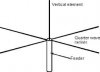
Here is a picture of a vertical antenna. It it were to be used as a quarter wave vertical for the FM band it would be about 30 inches long. If it were to be as a half wave vertical it would be about 60 inches long. Actually these lengths are just approximations tor the sake of a simple example.

This type of antenna is unbalanced.

An antenna constructed like this will have a feed point impedance of around 37 Ohms.
 

Attachments

  • QUARTER WAVE VERTICAL ANTENNA.jpeg
    QUARTER WAVE VERTICAL ANTENNA.jpeg
    5.3 KB · Views: 18
1/2 wave dipoles with a balun and 1/4 wave verts w/4 radials are the bomb. j-poles tend to be troublesome with feedline radiation even with a balun. I've never met a j-pole that I liked.
 
1/2 wave dipoles with a balun and 1/4 wave verts w/4 radials are the bomb. j-poles tend to be troublesome with feedline radiation even with a balun. I've never met a j-pole that I liked.

The j-pole antenna is pretty much binary. You either like them or not. There is not much middle ground.

They can be fiddly, and a lot of the plans on the internet are incorrect. I have built and used j-pole antennae from 40 meters (OK that is about 7 mHz) up through microwave frequencies and have had good luck.

You point about feed line radiation is true. I designed my j-pole antennae to include a counterpoise, less feed line radiation and a lower take off angle (angle of radiation).

All of the elements of a j-pole antenna are at DC ground and that is a definite plus for an antenna that is mounted outside and used with a good ground system.

Antennae are fun. I used to work for a ham radio antennae manufacturer.
 
JimJ[VT];4783893 said:
I know 1:1 current baluns are used a lot in ham radio. Often times, it's just a "choke balun" formed by a loop of the coax at the feedpoint, reducing common mode signals on the shield of the coax.


A 1/2-wave vertical and 1/2-wave dipole aren't the same antennas. A halfwave dipole is just its horizontal counterpart rotated vertically, and you're right, it's still 50 ohms. The vertical is just a halfwave radiator with "nothing else" (in quotes because that's a contentious point, you need to have some kind of ground or counterpoise in the equation at some point)


Because of the coax feed. Doesn't have to be, though...a lot of hams (myself included, when I get around to it) put up dipoles fed with balanced ladder line, so it stays balanced all the way back to the antenna tuner.


There isn't really a need, but a few loops at the feedpoint is easy to do.

I did not notice your post when I made my post.

A dipole antenna is a balanced antenna regardless of the type of feed line.

A ground plane vertical uses a quarter wave radiator, not a half wave radiator.
A half wave dipole is so called because the entire length is approximately one half wavelength. Each leg of the dipole is a quarter wave length long.

Some of the vertical FM broadcast band antennae available on the internet are in fact half wave vertical antennae, with an overall length of about 58 inches or a little less. The coil used to match the impedance to either 50 or 75 Ohm coax provides a small amount of inductive loading resulting in a slightly shorter vertical radiator. The advantage of this type of antennae is a slightly lower take off angle than a quarter wave vertical and this will result in slight increase in the "gain" of the antennae.

A half wave (about 58 inches for the FM band) radiator used as a simple ground plane antenna without some form of matching network will not work up to its full potential. Because of the mismatch, the shield of the coax may function as part of the antenna and give the impression that it does in fact work.

Because of the skin affect of RF, a piece of coax connected directly to a balanced antenna actually functions as three wires. The center conductor, the inside of the shield and the outside of the shield.

The outside of the shield of the coax will act like an antenna, instead of just a feed line. That means it is free to pick up wanted or unwanted signals. In the case of trying orient a dipole antenna for the least amount of multi-path signal reception, this unwanted antenna will cause problems. Also since the outside of the shield of the coax is acting as an antenna, it is free to pick up noise along it full length. So if you have moved your antenna away from something like a computer or switching power supply so that it does not pick up as much noise, that move will not be as affective.

Having said all of this, when it comes to receiving an FM broadcast signal, sometimes a random "chunk" of wire will work well enough. But when conditions are rough, and understanding of antenna design will go a long way to improving your enjoyment of FM.

 
Thanks for that comprehensive review, JBL! I have it bookmarked. Looks like I could use that 1:1 75 ohm Balun. Wonder where to get one?
 
Yes, you have found the correct way. The length of the coax in the coil is important for the best results. If you can find the velocity factor of your coax you should use it in your calculation of the length.
 
Since I have satellite TV and no need for a TV antenna, I use the TV antenna for FM, it gets pretty good reception
 
Since I have satellite TV and no need for a TV antenna, I use the TV antenna for FM, it gets pretty good reception

Yes, it should. FM lay between channels 6 and 7 of the old TV channel assignments, so it's right in the center of the antenna's bandwidth. Until recently I was doing the same thing myself.
 
Back
Top Bottom