• The move to the new server is done. There are some software and database maintenance updates in process. This has us passing the hat around to help out. We appreciate any donations. Seriously, even a dollar helps. The payment page may be found here - https://www.audiokarma.org/support.html

Need circuit Diagram KR-44 SL

VintageDutch

Active Member
Hello all,

This weekend my Vintage receiver family collection got a new member addition..
The Kenwood KR-44 SL

It had FM, AM LW 1,2,3 Aux and a Phono section..and a Tape out/input..

Look fair, Mint face plate, needs cleaning and partial restoring (recap)... Best of all... It sort of works...
is only Mono, there is a big difference in volume output left and right...somebody put in a wrong size fuse...
Caps are not really fresh and the Dial cord need replacing...(almost broke)

I have seen the receiver family it belongs to but never with these 3 Shortwave bands.. It is nice receiver..and what I understand (not confirmed yet) it could be a low number manufactured apparatus...

To be not working blindly I would like to have a reference copy of the circuit Diagram.

Usually I can find these problem free, but in this case I just can't find it... (confirming the low numbers?)
Yes, I can find the KR-44 but not the SL version.

I probably has parts and circuits in common but board numbers say other wise.

So any one have a good free (Hey.. i'm Dutch :-) ) download link, or willing to send a copy by e-mail? Would be very helpful and appreciated..

Some KR-44SL porn? Yes sir!!


When it came in..... No lights..and missing wooden side panels (for what I have seen)
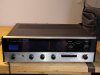
IMG_20210821_142145084.jpg

Did a little light bulb replacing and face plate / scale cleaning
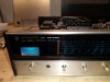
IMG_20210822_212823696.jpg
Still need to have to put in a light spreading filter as you can see....but I cleaned up nicely...
IMG_20210822_224539622.jpg

In side still dusty :-)

Still needs lots of work.... But It is a nice little receiver... no top segment but nice.

Any help is welcome!!
 
Register to hide this ad
Thanks all for the reply's

It seems there are indeed several trio and kenwood models series very close in external looks but on the inside is a different story

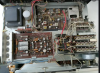
This is the inside of the KR- 44SL as I know it.44sl.PNG

This the KR-44 44.PNG

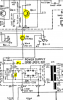
As far as I can see the poweramp might be the same circuit as is the supply but it surely uses different PCB numbers and chassis layout (and a different tuner section)....

But... the good news is...I have found the circuit diagram!!!.... It was via a "pay for my service" type website witch showed a preview in full size op the circuit... That's is what I need for reference...
While uploading it here to AK it even gave file to large error...so I had to reduce it ...If you want or need the full size... let me know I'll email it..

sm_kenwood_kr-44sl_copy.jpg

Again thanks for the brains and the answers... the @Semanon reaction was a good hint to find the diagram.. and @KENWOOD RULZ post made the final difference to me...


My Kenwood / Trio family is steadily growing I will list soon in the appropriate post
 
Had a near escape (hopefully)

I was listening to that little gorgeous KT 44SL... Still no stereo...did some voltage checks... Suddenly the Signal meter light bulb started flickering....heard some vague pop corn popping...... after that is was all good (i thought)..
not even a minute later... the special smell of a transformer heating up... and sure enough...the proof was presented that this little Receiver was made by Native Japanese young man in there teens and still smoking....

I really never ever have pulled a power cord so fast...

In less then 2 seconds the amp was outside...enjoying a cool breeze...after some hour or so... took it back in...hooked it up after some safety measurements.... looks like I was in time....

After some further inspection... some joker at one time soldered the supply wires to the Stuts but did not think about the chassis ... it was to close for comfort... and sure as Hell.. my measurement moved the little Supply PCB. shorting the AC transformer wires to ground (Chassis)

In the picture... the black wire the way the factory did it... The red soldered wire by some Goof... In the blue circle you see the soldering... in the red circle... see where the short occurred (I pulled up the wires)

transfomer wires.png

Will test more..and correct the hazardous wire soldering...

Mind you... soldering in it self is not dangerous but wires left blank close to metal is...
 
Well... did some serious testing last night... Although the smell is still strong... the transformer stays "cold" while the receiver is working near normal...

SO I thought to go ahead and start trouble shooting the FM stereo and FM Signal meter problem.

Found several caps on the receiver/MPX board that where dead, blown, leaky or only 10% of there value...replaced them all to be sure.. But the problems remain the same..
The stereo light bulb is ok. The Voltage is also strong at 20 volts with no bulb burning but drops to low 3 volts when the bulb is forced to light up.. so replaced the bulb driver transistor, but that was last night at 01.00 hours...
upload_2021-8-26_11-17-39.png
I hope I can replace the supply resistors tonight at I really hope this stabilizes the voltage towards the mentioned 8 volts.
Also planning on replacing the Boards trim pots... after being open for so many years they are likely to have a problem of some kind..

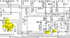
The Signal meter is a different story... It works in AM LW and SW mode but not in FM mode... seems it has a different circuit for FM... can not find any correlation with the 8 volt line...however I'm know to make mistakes since i'm human...
upload_2021-8-26_11-18-46.png
SO any pointer here could help...

Many thanks for al the thinking
 
After a mighty long time of doing very less new repairs (but still buying Vintage gear) it is time for an update on this little nice Receiver...

Long story short..... IT is back from the (almost) dead...

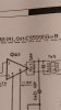
Short story long... after replacing the FM input transistor it turned out that half of the CS5995b was gone to CS5995b heaven
IMG-20211119-WA0018.jpegIMG_20211119_201453782.jpg IMG_20211119_201533698.jpgThat's where it was seated..

It took some doing before I realized it's replacement was a very "ordinair" LM 703 ... I could have opted to find the old, round LM703...Turned out there was only 1 in the whole of Europe....In Spain... would have cost me About 25 euro and some shippment of......37 euro!!!!
That is crazy money..

So I have opted for the standard 8 Pin Dil LM 703... For testing I resolved to "hard wire" it in...And it works flawless!!!! I have run the Receiver now a 2 months straight Small wire Antenna... And it is selective, picking up a lot of FM stations in Stereo...still needs some adjustment and such but overal I'm very happy with this result.

Since I have allot on my plate right now it terms of Remodeling a new home for me and my Girlfriend and after that setting up my new Workshop again I'm choose to Go for longterm Testing this hard wire solution and develop a nice PCB later on and create a permanent solution and maybe offer it as a complete replacement board for smal change..at some point in time.


SO problem solved so far!>>>
 
Back
Top Bottom