• The move to the new server is done. There are some software and database maintenance updates in process. This has us passing the hat around to help out. We appreciate any donations. Seriously, even a dollar helps. The payment page may be found here - https://www.audiokarma.org/support.html

Need for Stage 2 Schematic

BillDWY

New Member
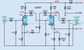
Does anyone have they can share, a great sounding highest quality second stage amplification schematic for a 12AU7A or 12AT7A tube through a tone circuit then into 6U8A phase inverter? My pre amp (schematic attached) gives and output at about line level of 0V RMS to 2.3V RMS.

PreAmp.jpg
 
Register to hide this ad
High gain, low current stuff like a 12AX7 are not what I pick up for line level work. I am pretty sure you will have the devil of a time finding a schematic with tone controls built around a 6AH4, or 12B4, or even less likely, a triode-strapped EL84.

If I were to decide frequency contouring was needed, I'd build a solid gain stage with low output Z, and a gain between 5 and 10, and apply a solid graphic equalizer into the chain between the linestage and the amplifier. Depending on your source level, extending the upper limit on gain to 20 would be an option; the triode-strapped EL84( either a 6P14P or the 6P15P ). The 6P15P is not an EL84 equivalent, but per data from Klausmobile, as a triode the two are identical. Type 12A4 is a relative of the 12B4 but with higher mu, think of it as a super-6SN7. And pin-compatible with 12B4 if you wish further experimentation.

IOW, lots of stuff out there to deliver something to eclipse the performance of a 12AX7 linestage... :)

Douglas
 
Thank you Douglas for your reply. Years ago I acquired two sleaves of new in the box of ECC83 12AX7 TELEFUNKEN SMOOTH PLATES. They have been setting on the shelf crying to be put to work for 25 years. All were tested on my Amperex AT1000 as new 100%+. Have now found some time to build a killer push pull amplifier. The amplifier stage will be using New Old Stock Western Electric 300B’s and (? On output transformers). I do have a very good tone circuit to use in the second stage output, I have used before with wonderful results. I need help on this second stage. :)
 
I might consider making this modular. Build the power amp as just a power amp. Tone controls go in a preamp, built on a different chassis.
 
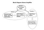
Thank you gadget73 for your reply. Yes in fact that is what I’m doing. It will be 3 modular sections. Section 1 will be the preamp with inputs for RIAA equalization on vinyl, reel to reel tape, DAC and CD. All switched (my problem part stage 2 of section 1, with tone and volume side solved). Then into Section 2, the amp 300B plus 8 ohm opt out to speakers. Section 3 is the power supply.
 
Do I understand correctly, you're planning to drive push-pull 300Bs with a 6U8? Maybe you could sketch a simple block diagram of the system you're planning (from high-level source input to the 300B output)? That would clarify a number of points, including the amount of gain needed in each section and signal swings. Those 12AX7s you've got could fit in well around a Baxandall tone circuit or phono preamp, but they're not well suited to much else IMO.

Jack
 
A 6U8 tri/pent front end to a 300B would not be the usual thing you see for sure. Need a lot of voltage swing to drive a pair of 300b, I don't honestly know if one of those is up to the task. I think the most i've ever seen one of those asked to do is probably EL34 tubes in an ST-70, so ~70v grid to grid. 300B in datasheet push-pull is nearly double that. 350v on the plate calls for -67.5v of bias, grid to grid drive is essentially 2x the bias voltage.
 
A 6U8 tri/pent front end to a 300B would not be the usual thing you see for sure. Need a lot of voltage swing to drive a pair of 300b, I don't honestly know if one of those is up to the task. I think the most i've ever seen one of those asked to do is probably EL34 tubes in an ST-70, so ~70v grid to grid. 300B in datasheet push-pull is nearly double that. 350v on the plate calls for -67.5v of bias, grid to grid drive is essentially 2x the bias voltage.
I like that idea thank you gadget73. Will start working with your idea. Any thoughts about my problem on stage #2?
 
The Marantz 7 preamp uses all 12AX7's around tone control circuitry and it also has a cathode follower for an output.
 
I don't own anything with tone controls that I actually think really sound good, so I honestly don't know. Most of them boost and cut too close to the midrange and instead of being bass and treble controls, they end up being boom and honk controls.
 
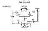
Thank you, Jack for your reply. Attached is the block diagram and tone control schematic.
I just received a part that was delayed by the PO, so I'll be on the bench for a while. However, I think the best approach here is to start at the outputs and move backwards to account for gain and current requirements. Looking at just the output section (as if you were building a straight power amp), here's an approach that I think has a lot of merit. Difficult to read, but it's all there. This uses a long tail pair to drive two 6SN7 voltage amps in push-pull to the 300B grids. This driver design should have a lot of headroom and provide a solid, low distortion signal for the output tubes.

Push-Pull 300B at Bonavolta

Jack
 
hm, kind of a hybrid of a Mullard design and a Williamson.

actually a regular Williamson front end should work too if you're more inclined to that style of inverter.


neat to see a 300B design actually pushing those tubes to something like they are really capable of. Most things seem to use them in low power mode but its a reasonably stout tube. 36 watts of plate dissipation.
 
hm, kind of a hybrid of a Mullard design and a Williamson.

actually a regular Williamson front end should work too if you're more inclined to that style of inverter.


neat to see a 300B design actually pushing those tubes to something like they are really capable of. Most things seem to use them in low power mode but its a reasonably stout tube. 36 watts of plate dissipation.

The LTP with diff amp will have less gain, but more potential voltage drive, than the Williamson. The LTP inverter can output more swing per side, than a cathodyne/split load, given the same B+ voltage. But, the LTP has half the gain of a standard first-tube gain stage (assuming the same tube) in a Williamson.

If all 6SN7s were used- assuming a gain of about 14 for a 6SN7 in circuit- that would make for an open-loop gain of about 7 x 14 = 98 for an LTP driving a diff amp. A Williamson front end would be about 14 x 13 or so (a little loss for the split load) = 182 or so.

Closed loop gain (with feedback) to have 1.5V input sensitivity at the input of the amp at max output (output of the inverters 80V peak) would be (80/1.4)/1.5 = about 38. So, the feedback ratio with the LTP driving the diff amp would need to be 98/38 = about 2.57, or about 8.2dB feedback. For the Williamson- it would be 182/38 = 4.78, or 13.5dB. Both feedback ratios make sense, in the real world. With triode output- feedback is less necessary in great amounts, due to the lower inherent output impedance- even the 8.2dB would probably be just fine, to get good speaker damping.

EDIT: Looked at the Bonavolta schematic- he's saying 10dB feedback, with 3V input sensitivity. That is quite close to what would happen with my calculations above, given 8.2dB feedback for 1.5V input sensitivity. Within normal real-world gain variation ranges, for sure.

Regards,
Gordon.
 
Last edited:
The LTP with diff amp will have less gain, but more potential voltage drive, than the Williamson. The LTP inverter can output more swing per side, than a cathodyne/split load, given the same B+ voltage. But, the LTP has half the gain of a standard first-tube gain stage (assuming the same tube) in a Williamson.

If all 6SN7s were used- assuming a gain of about 14 for a 6SN7 in circuit- that would make for an open-loop gain of about 7 x 14 = 98 for an LTP driving a diff amp. A Williamson front end would be about 14 x 13 or so (a little loss for the split load) = 182 or so.

Closed loop gain (with feedback) to have 1.5V input sensitivity at the input of the amp at max output (output of the inverters 80V peak) would be (80/1.4)/1.5 = about 38. So, the feedback ratio with the LTP driving the diff amp would need to be 98/38 = about 2.57, or about 8.2dB feedback. For the Williamson- it would be 182/38 = 4.78, or 13.5dB. Both feedback ratios make sense, in the real world. With triode output- feedback is less necessary in great amounts, due to the lower inherent output impedance- even the 8.2dB would probably be just fine, to get good speaker damping.

Regards,
Gordon.

Thank you very much, have followed you for many years. Remember your work on the Heathkit AA-100. I followed your changes in the AA-100 years ago and was impressed with the sound improvement. Still have the unit. Will check into your advice.
 
Thank you very much, have followed you for many years. Remember your work on the Heathkit AA-100. I followed your changes in the AA-100 years ago and was impressed with the sound improvement. Still have the unit. Will check into your advice.
GordonW; Do you have any ideas for stage #2 of the preamp section?
 
I don't own anything with tone controls that I actually think really sound good, so I honestly don't know. Most of them boost and cut too close to the midrange and instead of being bass and treble controls, they end up being boom and honk controls.
I have found throughout my long audio journey that the "room" plays a significant part in what you hear from your chosen loudspeaker system. Every room is different and will have it's own sonic signature and influence the final sound we perceive as a reproduction of music. I agree that the traditional bass & treble turnover frequencies (100Hz/10kHz) for shelving type controls are not the best, but they can be effective after EQ/PEQ is applied to the room to get a flat response or "room curve". Then, when a little bass/treble boost/cut is needed, these shelving type controls can be (graciously) used without sounding offensive.

I tried the purist approach long ago using minimal tone controls and/or line stage only, etc. I quickly found that the music sounded like a table top radio. I have always thought that music listening always needs some type of frequency compensation for playback in a room. Granted, some speakers seem to sound good in all rooms with no EQ/PEQ but they are not very common.

Lately, I have been experimenting with DSP and the results have been quite astonishing. For a hardcore analog guy, I have resisted inserting a DSP into my 2 channel music signal chain, but for home theater I am fine with it. Anyway, a thread in another section of this forum got me thinking of using a home theater receiver (my preference is Pioneer) with DSP such as the Pioneer with MCACC. This particular version of the MCACC will compensate for speaker distance, room EQ, standing waves (reverberation) and phase control. The Full-Band Phase Control attempts to correct phase/group delay through passive crossover networks. This experiment has elevated my 2 channel listening experience to a whole new level with no penalty. The home theater receiver I am using (VSX-92TXH) has pre-outs so I can still use my favorite 2 channel amp and bypass the internal home theater amp. The preamp is dead quiet and has excellent sound quality. I am still amazed that after going through all of the analog/digital signal path that the final sound is better than just a simple (short signal path) line stage preamp. If I had not tried it and somebody told me about it, I would have said you are full of BS.

DSP is the way to go, but there are so many paths to DSP you will have to do your home work to see which path is right for you.
 
Room is definitely huge in this. Its not that I'm a hard core purist but I've just not had a lot of love for traditional 2 knob adjustments. I don't tend to love loudness correction in most things either, too much bass boost.
 
Back
Top Bottom