• The move to the new server is done. There are some software and database maintenance updates in process. This has us passing the hat around to help out. We appreciate any donations. Seriously, even a dollar helps. The payment page may be found here - https://www.audiokarma.org/support.html

Need Help for Schematic Interpret

ASRHTB

Member
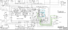
I have Akai GX 600DB that is not erasing and recording. I want to start step by step with erasing the tape problem. Here is erase operation schematic:

Here is the service manual pdf.

erase head.png

erase head 2.png

First of all, I could not get any AC signal generated with the L3. Also, I have checked all of the components, which seems to be working just fine. I have cleaned the record switch, which triggers by a selenoid, and tested it with the multimeter's continuity test. It works just fine. Heads are also fine.

Can anyone explain what TR6 and TR7 do with L3 to generate a 116.9 AC signal? I have measured 24.5V DC instead of 18.6V DC. Is this might cause this kind of problem?

I do not know what else I should do... When I have finished this problem, I will start to fix the recording side of the problem.
 
Register to hide this ad
Its the oscillator amplifier. Basically it feeds its own output back to itself to create the bias signal. If thats not running, there won't be anything for those transistors to do. If C24 is bad it will shut this whole thing down. Same if any of the coils in that transformer are open.

High voltage is just because its not doing any work. Voltage drops across R38 when those transistors are drawing current.
 
Its the oscillator amplifier. Basically it feeds its own output back to itself to create the bias signal. If thats not running, there won't be anything for those transistors to do. If C24 is bad it will shut this whole thing down. Same if any of the coils in that transformer are open.

High voltage is just because its not doing any work. Voltage drops across R38 when those transistors are drawing current.

Thank you for your response, I have checked C24 and it is fine. Also, I have checked the coils in the transformer with a multimeter it seems good too. According to service manual reference, you might see picture below, I have checked the coil's dc resistance and results:

between 1-3: around 0.1 ohm
between 4-6: around 0.5 ohm
between 7-9: around 8.1 ohm

It seems the first two coils result differently but it might happen because of my multimeter (Unı-t Ut 890D+) (it is too simple which generally measures with some error.)

coil.png
 
The transistors switch on and off synchronized to produce the HF AC bias. You need to measure AC, not DC on the transistor emitters (R32 & 33) to see if they are working. No bias means no erase or record. It is the same problem. The frequency should be whatever the bias frequency is specified at. If your multimeter is a basic one, then coil resistance measurements that low are certainly not accurate, however since both coils for the transistors inputs appear about a dead short, then the transistors or the coils appear to be bad.
 
Last edited:
The transistors switch on and off synchronized to produce the HF AC bias. You need to measure AC, not DC on the transistor emitters to see if they are working. No bias means no erase or record. It is the same problem. The frequency should be whatever the bias frequency is specified at. If your multimeter is a basic one, then coil resistance measurements that low are certainly not accurate.

OK. I will try it in the first place.
If R38 burned (shorted), may it cause this kind of problem, and how to check if TC1 or TC2 is working or not?
 
fair bet the diode check function will tell you if the transistors are duds. If they aren't open or shorted, its pretty unlikely they are bad. They'll have to come out for this, the transformer coils will screw up your readings otherwise.


If R38 were bad you would have no voltage at the transistors.
 
fair bet the diode check function will tell you if the transistors are duds. If they aren't open or shorted, its pretty unlikely they are bad. They'll have to come out for this, the transformer coils will screw up your readings otherwise.


If R38 were bad, you would have no voltage at the transistors.

Transistors are not shorted or opened. I will try to change them. I hope they are in bad condition. I will replace then recheck it.

Isn't it possible that r38 shorted? Because I do not see any voltage drop at all. I will check it soon and return it to you.
 
fair bet the diode check function will tell you if the transistors are duds. If they aren't open or shorted, its pretty unlikely they are bad. They'll have to come out for this, the transformer coils will screw up your readings otherwise.


If R38 were bad you would have no voltage at the transistors.

I have checked transistors which there were 1247A instead of 2sc1211d (according to the service manual). However, the legs of 1247A ECB should be as EBC as I understand from the schematic. I have MPSA06 I have given it try but nothing changed. There is no erasing function that works at all...

Also, there was no AC signal over there (before or after transistor replacement).
 
Resistors almost never fail shorted. You can measure it, but I have yet to encounter one that went bad that way. Honestly even if it were shorted, I doubt it would prevent it from working. The transistors would just run too hot and probably burn themselves out.

Are the new transistors installed so the legs match the schematic? I recently fought with something for weeks because I read the datasheet wrong and got the part in wrong.
 
Resistors almost never fail shorted. You can measure it, but I have yet to encounter one that went bad that way. Honestly even if it were shorted, I doubt it would prevent it from working. The transistors would just run too hot and probably burn themselves out.

Are the new transistors installed so the legs match the schematic? I recently fought with something for weeks because I read the datasheet wrong and got the part in wrong.

I think it is something else from the resistor problem. I will try to change legs, but according to the schematic, the emitter side should connect the 3.3-ohm resistor and collector at the middle. Anyway, I will give a shot to switch legs. I have alternative transistors.
 
gadget73, perryinva, It passed some time. However, I have managed to work the recording channel again (one of its channels not working properly..), but erase head is not working. What could you suggest? I don't give the L3 oscillator coil a chance to be faulty. Can it be? If the oscillator coil is defective, where can I find it? I could not find a similar component.
 
Hello,

The problem was C28 (4.7 uf 25V) capacitor. I wasn't expecting that to come up. When I replaced C28 oscillator side start working... This must a joke...

Resistors almost never fail shorted. You can measure it, but I have yet to encounter one that went bad that way. Honestly even if it were shorted, I doubt it would prevent it from working. The transistors would just run too hot and probably burn themselves out.

Are the new transistors installed so the legs match the schematic? I recently fought with something for weeks because I read the datasheet wrong and got the part in wrong.
 
Back
Top Bottom