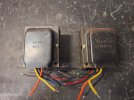
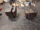
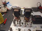
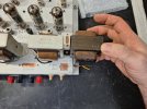
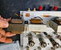
I am certain that this mystery transformer swap away from the stock OPTs will be an improvement.
One of the dirty little secrets about the 9300 is that the stock transformers suck. They are pretty large, but the problem is that they have a nasty resonant tendency, and perform so poorly at high frequency, making it difficult to adequately maintain amplifier stability without impinging badly upon the audio bandwidth of the amplifier. Dave G had to employ masterfully a significant amount of frequency limiting and general hand holding to get the amplifier to perform as well as the final result does. The fact is, all of that frequency limiting and stability tuning is custom fit to the stock transformers, and swapping them out requires reworking a lot of that to get any significant improvement with the new transformers (beyond just the better impedance match). Leave that limiting in place, and you might incur new problems.
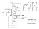
I have upgraded the DG 9300 model (with cathode EFB) to much better (still console class) output transformers from an RCA RS177A that offered 4 and 8 ohm output taps, and also a better set of Musical Power Supplies OT20PP (VC87 version) with 4,8, and 16 ohm taps. Both were 8K plate to plate primary impedance, and once the amplifier was re-tuned, offered more or less similar significant improvement over the stock transformers. I have attached the schematics for both of those modifications, and will discuss them.
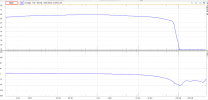
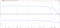
All three sets of similar sized transformers had more or less parity performance on the low end, rolling off at around 40Hz more or less. The dramatic improvement was at the high end. Frequency response upper roll-off for the stock iron was only to 20kHz at 1 Watt, and a miserable 10kHz at power, but both the RCA and MPS transformers were good up to 50kHz even under power. In order to achieve this better high frequency performance, the frequency limiting and stability tweaks had to be adjusted, and the final recipe is almost identical for both the RCA and MPS transformers, and stand a decent chance of being at least somewhat close for your mystery transformers.
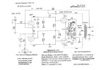
First, the original Gillespie 9300 schematic below with cathode EFB, stock transformers, which includes the "bullet proof" EFB update. The first bit of frequency limiting is the 47k grid stopper between the input and the 6EU7 grid- that has a f3dB of about 20kHz, so passes just the audio band into the input, but in doing so is degrading audio quality well below that f3dB point. Next is the "shelf" network of 390pF and 1500 ohms hanging off that 6EU7 grid- that is VERY heavy handed, but must be to control the amplifier- As built the shelf begins to activate at only 8.1kHz and severely reduces the triode gain above that to avoid oscillation. It is not simple calculating the exact impact on bandwidth because of the corrective effects of negative feedback, and the transformer limitations also contribute, but with experimentation on the better transformers it becomes evident that if left it will severely limit frequency response. The amplifier uses a modest amount of negative feedback, 12dB, as set by the 1800 ohm feedback resistor from 4 ohm tap. Note there is no frequency compensation or "phase advance" cap parallel that 1800 ohm feedback resistor- the output of the transformer performs too poorly at high frequency use that method. Instead, the 47pF capacitor from the 6BQ5 plate to the feedback path provides a "clean" high frequency source for that compensation.
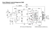
Next, we compare that original schematic to the one tuned for the RCA and MPS transformers shown below. The 47K grid stopper with 20kHz f3dB roll-off has been replaced with a 10K and an explicit 47pF miller stabilizing capacitor. This has a roughly a 74kHz f3db roll-off, blocking the higher frequencies that contribute to oscillation but leaving the audio band untouched. The shelf network has been reduced- with 120pF and 10K, which does not activate until around 23kHz, and does not reduce the triode gain as dramatically. Although the feedback resistor is still 1800 ohms, negative feedback is increased from 12dB to 14dB because it is now coming from an 8 ohm tap. This provides for lower distortion, but the amp is still plenty sensitive, now driven to maximum power with 750mVrms input (600mVrms before). The 47pF "plate feedback" cap has been removed, and the transformer source is clean enough to use the standard compensation cap parallel the feedback resistor. High frequency response was found to be most flat with 390pF for the MPS transformer, and 500pF for the RCA. With the changes mentioned so far, for the MPS transformers, the amplifier was now extremely stable with output open and up to a 0.1uF purely capacitive load. The RCA transformers were slightly less stable, breaking into oscillation when unloaded with only a .022uF capacitive load. Rather than make the shelf network more aggressive I used a zobel network connected across the 8 ohm output of .1uF film cap in series with a 47 ohm resistor. This zobel has an f3dB of 34kHz and only lightly loads the output, yet now allows the amp to be equally stable open with 0.1uF capacitive load and still achieve an upper roll-off in the mentioned 50kHz region.
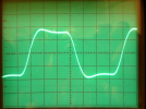
The difference in high frequency performance is visually dramatic. On the left, is Dave's original scope shot, with the comment:
"10 kHz square waves still display a slow rise time indicating the reduced supersonic response of the original OPTs, but note they are quite civilized now compared to that from the original design."
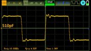
On the right is the same 10kHz square wave with the RCA transformer, and that of the MPS transformer looks almost identical.
I will note that not every transformer is wound identically- although the color codes of the leads may be identical, the polarity of the windings they are connected to may not be the same. If at power-on you get severe oscillation (hopefully you have a dummy load, so can "see" it rather than hear it) you may have to reverse the blue and brown leads.
I am confident that if you apply these same basic modifications to your 9300 you will achieve most if not all of the improvements achieved with the transformers I used here. If, worst case scenario, the mystery transformers are not as good and the amplifier oscillates when unloaded, the more heavy handed 47K grid stopper can easily be returned, and if really needed the heavier handed original shelf network. There are plenty of hobbled 9300's running around out there, and people still enjoy them (I did), so, this is a "can't lose" scenario with lots of likely upside.